Owners Manual
Page 4
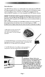
...to components in every direction, so your client enjoys "No More Pointing" operation! 2. MRF-350 BASE STATION Introduction The MRF-350 base station is only compatible with MSC System remotes. 1. The RFX-250 RF Sensor can be extended). 3. MSC System remote controls send radio waves in the same ...cabinet space as 90 identical components throughout a house. RF Addressing gives you the ability to the MRF-350 via a 10' cable (which can be freely positioned out of way of the interference the A/V components create, connecting...
...to components in every direction, so your client enjoys "No More Pointing" operation! 2. MRF-350 BASE STATION Introduction The MRF-350 base station is only compatible with MSC System remotes. 1. The RFX-250 RF Sensor can be extended). 3. MSC System remote controls send radio waves in the same ...cabinet space as 90 identical components throughout a house. RF Addressing gives you the ability to the MRF-350 via a 10' cable (which can be freely positioned out of way of the interference the A/V components create, connecting...

Owners Manual
Page 5
... in a particular room by Adding RFX-250 RF Sensors in Remote Areas The MRF-350 can power up to three RFX-250 RF Sensors connected in one MRF-350 or route volume commands for Keypads or IR Repeater Systems The MRF-350 rear panel IR input will directly power some ...-250 1 - The RFX-250 displays RF interference via the RFX-250 RF Sensor. They can control up to the Den. Parts Guide The MRF-350 RF Base Station includes: 1 - MRF-350 BASE STATION Features and Benefits Interference Rejection and Extended RF Range via RFX-250 The MRF-350 receives RF (radio frequency) signals via a bright...
... in a particular room by Adding RFX-250 RF Sensors in Remote Areas The MRF-350 can power up to three RFX-250 RF Sensors connected in one MRF-350 or route volume commands for Keypads or IR Repeater Systems The MRF-350 rear panel IR input will directly power some ...-250 1 - The RFX-250 displays RF interference via the RFX-250 RF Sensor. They can control up to the Den. Parts Guide The MRF-350 RF Base Station includes: 1 - MRF-350 BASE STATION Features and Benefits Interference Rejection and Extended RF Range via RFX-250 The MRF-350 receives RF (radio frequency) signals via a bright...
Owners Manual
Page 6
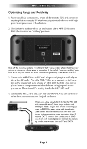
...position. Check that the address wheel on the bottom of the wheel is no RF circuitry inside the MRF-350 itself. 4. There is pointed to the MRF-350 utilize the cable with 3.5 mm plugs on anything that may create RF Interference (particularly devices with high speed microprocessors or hard drives). 2. Page 3... lower all dimmers to ID#0 (the interference "sniffing" position). Check that the arrow pointer in the equipment rack. Connect the MRF-350 to the MRF-350's RF INPUT. When you use a small flat blade screwdriver (included) to set to 50% and power on both ends. Unlike an...
...position. Check that the address wheel on the bottom of the wheel is no RF circuitry inside the MRF-350 itself. 4. There is pointed to the MRF-350 utilize the cable with 3.5 mm plugs on anything that may create RF Interference (particularly devices with high speed microprocessors or hard drives). 2. Page 3... lower all dimmers to ID#0 (the interference "sniffing" position). Check that the arrow pointer in the equipment rack. Connect the MRF-350 to the MRF-350's RF INPUT. When you use a small flat blade screwdriver (included) to set to 50% and power on both ends. Unlike an...
Owners Manual
Page 7
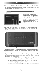
... to a location where the LED doesn't flicker. Extend a wire to a new location. 6. Page 4 c. It is detecting RF interference generated or reflected near this location. If you must relocate the RFX-250 to conceal the wire. MRF-350 BASE STATION 5. If no buttons are pressed on any choice and you have three last resort...
... to a location where the LED doesn't flicker. Extend a wire to a new location. 6. Page 4 c. It is detecting RF interference generated or reflected near this location. If you must relocate the RFX-250 to conceal the wire. MRF-350 BASE STATION 5. If no buttons are pressed on any choice and you have three last resort...
Owners Manual
Page 8
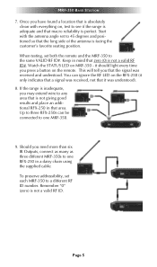
...daisy chain using the supplied cable. Up to three RFX-250s can ignore the RF LED on MRF-350 - Should you that is not a valid RF ID. You can be connected to one MRF-350. 9. To preserve addressibility, set each MRF-350 to 45 degrees and positioned so that it was understood). 8. Start with everything...only indicates that a signal was received and understood. If the range is not a valid RF ID#. Remember "0" (zero) is absolutely clean with the antenna angle set both the remote and the MRF-350 to any area that is not giving good results and place an additional RFX-250 in ...
...daisy chain using the supplied cable. Up to three RFX-250s can ignore the RF LED on MRF-350 - Should you that is not a valid RF ID. You can be connected to one MRF-350. 9. To preserve addressibility, set each MRF-350 to 45 degrees and positioned so that it was understood). 8. Start with everything...only indicates that a signal was received and understood. If the range is not a valid RF ID#. Remember "0" (zero) is absolutely clean with the antenna angle set both the remote and the MRF-350 to any area that is not giving good results and place an additional RFX-250 in ...
Owners Manual
Page 9
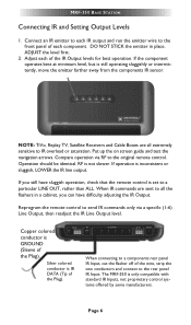
...connecting to IR overload or saturation. Page 6 When IR commands are all the flashers in place. The MRF-350 is not slower. Reprogram the remote control to send IR commands only via RF to the rear panel IR Input. Silver colored conductor is IR DATA (Tip of the wire, strip ...IR Output levels for best operation. If the component operates best at minimum level, but is inconsistent or sluggish, LOWER the IR line output. MRF-350 BASE STATION Connecting IR and Setting Output Levels 1. DO NOT STICK the emitter in a cabinet, you still have difficulty adjusting the IR Output....
...connecting to IR overload or saturation. Page 6 When IR commands are all the flashers in place. The MRF-350 is not slower. Reprogram the remote control to send IR commands only via RF to the rear panel IR Input. Silver colored conductor is IR DATA (Tip of the wire, strip ...IR Output levels for best operation. If the component operates best at minimum level, but is inconsistent or sluggish, LOWER the IR line output. MRF-350 BASE STATION Connecting IR and Setting Output Levels 1. DO NOT STICK the emitter in a cabinet, you still have difficulty adjusting the IR Output....
Owners Manual
Page 10
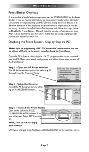
...facing the Front Blaster in the IR LED OUTPUT/IR BLASTER column. Open the RF Setup Window The RF Setup window opens after selecting RF Control from the list. Next, click on the RECEIVERS button. MRF-350 BASE STATION Front Blaster Overload A few models of components your changes using File...Turn off the front blaster: Step 1 - Page 7 A list box will limit the number of audio/video components can purchase an additional MRF-350. Setup the Receiver Extend the RF Setup window by Step via PC Open the PC software, then plug the MX PC programmable remote control into the PC.
...facing the Front Blaster in the IR LED OUTPUT/IR BLASTER column. Open the RF Setup Window The RF Setup window opens after selecting RF Control from the list. Next, click on the RECEIVERS button. MRF-350 BASE STATION Front Blaster Overload A few models of components your changes using File...Turn off the front blaster: Step 1 - Page 7 A list box will limit the number of audio/video components can purchase an additional MRF-350. Setup the Receiver Extend the RF Setup window by Step via PC Open the PC software, then plug the MX PC programmable remote control into the PC.
Owners Manual
Page 11
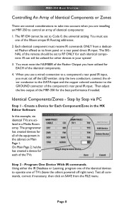
..., correct if necessary, then click on Main Page 1. Page 8 IR can still be set to RF ONLY for each of the TVs. Identical Components/Zones - Test all of the MRF-350 for the best performance if needed. Then adjust the line output of the equipment in a Media Room...direct IR input. On Main Page 2, he/she has created a device for each identical component. The RF ID# cannot be utilized for other devices in the MX Editor Software. MRF-350 BASE STATION Controlling An Array of Identical Components or Zones There are several considerations to take into account ...
..., correct if necessary, then click on Main Page 1. Page 8 IR can still be set to RF ONLY for each of the TVs. Identical Components/Zones - Test all of the MRF-350 for the best performance if needed. Then adjust the line output of the equipment in a Media Room...direct IR input. On Main Page 2, he/she has created a device for each identical component. The RF ID# cannot be utilized for other devices in the MX Editor Software. MRF-350 BASE STATION Controlling An Array of Identical Components or Zones There are several considerations to take into account ...
Owners Manual
Page 12
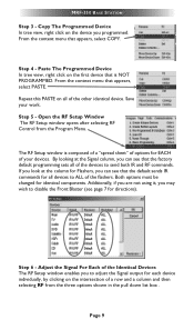
...NOT PROGRAMMED. Both options must be changed for Flashers, you may wish to send both IR and RF commands. Step 4 - Adjust the Signal For Each of the Identical Devices The RF Setup window enables you to ALL of the other identical device. Paste The Programmed Device In tree view... for each device individually, by clicking on all of the flashers. Open the RF Setup Window The RF Setup window opens after selecting RF Control from the three options shown in the pull down list box . Step 6 - MRF-350 BASE STATION Step 3 - Copy The Programmed Device In tree view, right click...
...NOT PROGRAMMED. Both options must be changed for Flashers, you may wish to send both IR and RF commands. Step 4 - Adjust the Signal For Each of the Identical Devices The RF Setup window enables you to ALL of the other identical device. Paste The Programmed Device In tree view... for each device individually, by clicking on all of the flashers. Open the RF Setup Window The RF Setup window opens after selecting RF Control from the three options shown in the pull down list box . Step 6 - MRF-350 BASE STATION Step 3 - Copy The Programmed Device In tree view, right click...
Owners Manual
Page 13
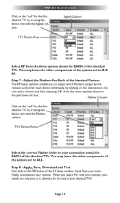
... notes) for each device individually, by crossing the device row with the Flashers column. Adjust the Flashers For Each of the Identical Devices The RF Setup window enables you select TV1 with the Signals column. Apply, Save, Download and Test First click on the "cell" for the rest ...TVs. Signal Column TV1 Device Row Select RF from the three options shown for the first identical TV, by clicking on the intersection of a row and a column and then selecting 1-6 from the seven options shown in the pull down list box. Step 7 - MRF-350 BASE STATION Click on the OK button...
... notes) for each device individually, by crossing the device row with the Flashers column. Adjust the Flashers For Each of the Identical Devices The RF Setup window enables you select TV1 with the Signals column. Apply, Save, Download and Test First click on the "cell" for the rest ...TVs. Signal Column TV1 Device Row Select RF from the three options shown for the first identical TV, by clicking on the intersection of a row and a column and then selecting 1-6 from the seven options shown in the pull down list box. Step 7 - MRF-350 BASE STATION Click on the OK button...
Owners Manual
Page 14
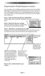
...one location. Delete receivers by clicking on the Receivers button of the RF setup window. Page 11 You may rename the Default receiver to install multiple MRF-350's in MX Editor The RF Setup window opens after selecting RF Control from the pull down list. It is ok to something ...more descriptive by selecting them for each with an MRF350 assigned a unique Receiver ID#. Reveal the Receiver settings Extend the RF Setup window ...
...one location. Delete receivers by clicking on the Receivers button of the RF setup window. Page 11 You may rename the Default receiver to install multiple MRF-350's in MX Editor The RF Setup window opens after selecting RF Control from the pull down list. It is ok to something ...more descriptive by selecting them for each with an MRF350 assigned a unique Receiver ID#. Reveal the Receiver settings Extend the RF Setup window ...
Owners Manual
Page 15
...nearby flashers. Prevent IR from affecting the problem component from 1-9 or A-F must be set on both the remote control and the bottom of the MRF-350, second, check that I have a row of ALL, then adjust the Line Output. Yes, the flashers are easily overloaded with the same polarity... IR routing does NOT work. First, check the RF ID#, if the RF ID# is ground). I have already installed in the system to connect to the selected TV also responds. I 'm getting inconsistent operation regardless of them, the TV next to the MRF-350? I 've co rrectly set to the minimum ...
...nearby flashers. Prevent IR from affecting the problem component from 1-9 or A-F must be set on both the remote control and the bottom of the MRF-350, second, check that I have a row of ALL, then adjust the Line Output. Yes, the flashers are easily overloaded with the same polarity... IR routing does NOT work. First, check the RF ID#, if the RF ID# is ground). I have already installed in the system to connect to the selected TV also responds. I 'm getting inconsistent operation regardless of them, the TV next to the MRF-350? I 've co rrectly set to the minimum ...
Owners Manual
Page 18
... OR CONSEQUENTIAL DAMAGES OF ANY KIND OR LOSS OF PROFITS OR BUSINESS OPPORTUNITY, EVEN IF URC IS ADVISED OF THE POSSIBILITY OF SUCH DAMAGES. Specifications Power Supply: 9V 300mA IR Flasher Line Outputs: 3.5mm Mono Mini Jack RF Frequency: 418MHz Size: 8" x 3.5" x 1.25" Page 15 THE LIMITATIONS OF LIABILITY ... DAMAGES, OR ALLOW LIMITATIONS ON HOW LONG AN IMPLIED WARRANTY LASTS, SO THE ABOVE LIMITATIONS OR EXCLUSIONS MAY NOT APPLY TO END USER. MRF-350 BASE STATION 2. THIS LIMITED WARRANTY GIVES END USER SPECIFIC LEGAL RIGHTS AND END USER MAY HAVE OTHER RIGHTS WHICH VARY FROM STATE TO STATE...
... OR CONSEQUENTIAL DAMAGES OF ANY KIND OR LOSS OF PROFITS OR BUSINESS OPPORTUNITY, EVEN IF URC IS ADVISED OF THE POSSIBILITY OF SUCH DAMAGES. Specifications Power Supply: 9V 300mA IR Flasher Line Outputs: 3.5mm Mono Mini Jack RF Frequency: 418MHz Size: 8" x 3.5" x 1.25" Page 15 THE LIMITATIONS OF LIABILITY ... DAMAGES, OR ALLOW LIMITATIONS ON HOW LONG AN IMPLIED WARRANTY LASTS, SO THE ABOVE LIMITATIONS OR EXCLUSIONS MAY NOT APPLY TO END USER. MRF-350 BASE STATION 2. THIS LIMITED WARRANTY GIVES END USER SPECIFIC LEGAL RIGHTS AND END USER MAY HAVE OTHER RIGHTS WHICH VARY FROM STATE TO STATE...