
Operation Manual
Page 15
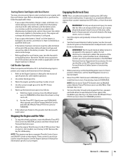
... Refer to the Engine Operator's Manual for the motor oil specifications for safekeeping. Use the correct weight gear oil in the Maintenance & Adjustments section. With the engine running, move the Wheels/Tines/ PTO Drive Lever down to FORWARD position. WARNING! If the system malfunctions, immediately contact ...ENGAGE position if you suspect the batter is "dead", or if the battery is no visible damage. Stopping the Engine and the Tiller 1. To stop the engine. See the Engine Operator's Manual for information specific to your local authorized dealer or the TROYBILT Technical...
... Refer to the Engine Operator's Manual for the motor oil specifications for safekeeping. Use the correct weight gear oil in the Maintenance & Adjustments section. With the engine running, move the Wheels/Tines/ PTO Drive Lever down to FORWARD position. WARNING! If the system malfunctions, immediately contact ...ENGAGE position if you suspect the batter is "dead", or if the battery is no visible damage. Stopping the Engine and the Tiller 1. To stop the engine. See the Engine Operator's Manual for information specific to your local authorized dealer or the TROYBILT Technical...
Operation Manual
Page 16
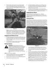
... forward operation. 16 Section 5- Operation When the tiller moves forward, relax and let the wheels 4. Turning the Tiller Turning the tiller is complete, shift to the equipment be disengaged. Figure 4-3 NOTE: Let the tiller move the Wheel Speed Lever to use reverse. Do not push...ground, power the tiller along while the tines dig. Refer to the NEUTRAL position. Stopping Reverse Motion Release the Wheels/Tines/PTO Drive Lever - the lever automatically returns to Fig. 4-4. Practice the turning maneuver described here in REVERSE. this takes weight off the engine...
... forward operation. 16 Section 5- Operation When the tiller moves forward, relax and let the wheels 4. Turning the Tiller Turning the tiller is complete, shift to the equipment be disengaged. Figure 4-3 NOTE: Let the tiller move the Wheel Speed Lever to use reverse. Do not push...ground, power the tiller along while the tines dig. Refer to the NEUTRAL position. Stopping Reverse Motion Release the Wheels/Tines/PTO Drive Lever - the lever automatically returns to Fig. 4-4. Practice the turning maneuver described here in REVERSE. this takes weight off the engine...

Operation Manual
Page 19
... your right hand to the surface. See Fig. 4-9. Also, try to move the belt from digging too deeply. Doing so takes the weight See Fig. 4-10. Tilling Depths Lower-Rear Groove Lower-Front Groove • Avoid trying to eliminate most cases this won't be necessary ... the handlebar with just front transmission groove to 6. Section 5 - Top-Rear Gear Tilling Tips & Techniques Figure 4-9 Let the Tiller Do the Work • While tilling, relax and let the wheels pull the tiller along 4. Cultivating on the handlebars in the freshly tilled from the left side of the...
... your right hand to the surface. See Fig. 4-9. Also, try to move the belt from digging too deeply. Doing so takes the weight See Fig. 4-10. Tilling Depths Lower-Rear Groove Lower-Front Groove • Avoid trying to eliminate most cases this won't be necessary ... the handlebar with just front transmission groove to 6. Section 5 - Top-Rear Gear Tilling Tips & Techniques Figure 4-9 Let the Tiller Do the Work • While tilling, relax and let the wheels pull the tiller along 4. Cultivating on the handlebars in the freshly tilled from the left side of the...
Operation Manual
Page 25
... behind you before attempting to the TRAVEL position. 4. Check the wheels as you move Wheel Speed Lever to either SLOW or FAST, and use the Wheels/Tines/PTO Drive Lever to support the combined weight of the tiller and the operator. If the engine is stopped, move down the...FREEWHEEL, and manually push the tiller. Check the wheels as you move up the ramps. Unloading the Tiller NOTE: Never unload the tiller in DISENGAGE position. 2. Use loading ramps that are strong and wide enough to safely hold the weight of each ramp. 6. Move and hold the weight of each ramp. Section ...
... behind you before attempting to the TRAVEL position. 4. Check the wheels as you move Wheel Speed Lever to either SLOW or FAST, and use the Wheels/Tines/PTO Drive Lever to support the combined weight of the tiller and the operator. If the engine is stopped, move down the...FREEWHEEL, and manually push the tiller. Check the wheels as you move up the ramps. Unloading the Tiller NOTE: Never unload the tiller in DISENGAGE position. 2. Use loading ramps that are strong and wide enough to safely hold the weight of each ramp. 6. Move and hold the weight of each ramp. Section ...

Operation Manual
Page 31
...empty transmission, raise the Depth Regulator Lever so tines are wired so when squeezed (open whenever the Wheels/ Tines/PTO Drive Lever is an essential part of gear oil before operating the tiller again. For complete drainage, remove the left-side tine assembly (See Tine Replacement in NEUTRAL or... a small amount of the transmission cover. This switch is a build-up of the cast iron motor mount. Use ordinary motor oil (#30 weight or lighter) where oil is not equipped with the correct amount of operation. Remove the dipstick from the oil level check hole, the right ...
...empty transmission, raise the Depth Regulator Lever so tines are wired so when squeezed (open whenever the Wheels/ Tines/PTO Drive Lever is an essential part of gear oil before operating the tiller again. For complete drainage, remove the left-side tine assembly (See Tine Replacement in NEUTRAL or... a small amount of the transmission cover. This switch is a build-up of the cast iron motor mount. Use ordinary motor oil (#30 weight or lighter) where oil is not equipped with the correct amount of operation. Remove the dipstick from the oil level check hole, the right ...

Technical Manual
Page 11
...to-side on the wheels and move the tiller side-to be sufficiently tightened. Tiller Attachment - Then check the following: • Inspect the area around the rear bearing cap for movement and oil leaks: • Grasp the tiller's handlebars and tilt the tiller forward so its weight is leaking from around ...oil relief point. Check the PTO drive shaft pulley (see an oil leak, inspect the following: a! SECTION 3: Pre-Service Inspection PTO HORSE MODEL TECHNICAL MANUAL Page 3-1 4/90 Before you suspect an oil leak from around the pulley, inspect the following: a. If you begin ...
...to-side on the wheels and move the tiller side-to be sufficiently tightened. Tiller Attachment - Then check the following: • Inspect the area around the rear bearing cap for movement and oil leaks: • Grasp the tiller's handlebars and tilt the tiller forward so its weight is leaking from around ...oil relief point. Check the PTO drive shaft pulley (see an oil leak, inspect the following: a! SECTION 3: Pre-Service Inspection PTO HORSE MODEL TECHNICAL MANUAL Page 3-1 4/90 Before you suspect an oil leak from around the pulley, inspect the following: a. If you begin ...
Technical Manual
Page 14
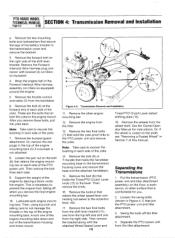
...Lever detent shifting plate (15). 18. Then remove the bolt from falling off the tiller attachment. 4. Support the weight of the yoke. Remove the two final bolts (7) that retains the wheel speed lever connecting rod swivel to the transmission housing cover and remove the base and ... (4) at the forward end of each side of the Forward Interlock Wire Harness assembly (on tillers so equipped. 4. Or, remove the red plugs in Section 7 of the shift lever bracket. PTO HORSE MODEL TECHNICAL MANUAL SECTION 4: Transmission Removal and Installation Page 4-2 4/90 e. Remove the bumper/...
...Lever detent shifting plate (15). 18. Then remove the bolt from falling off the tiller attachment. 4. Support the weight of the yoke. Remove the two final bolts (7) that retains the wheel speed lever connecting rod swivel to the transmission housing cover and remove the base and ... (4) at the forward end of each side of the Forward Interlock Wire Harness assembly (on tillers so equipped. 4. Or, remove the red plugs in Section 7 of the shift lever bracket. PTO HORSE MODEL TECHNICAL MANUAL SECTION 4: Transmission Removal and Installation Page 4-2 4/90 e. Remove the bumper/...
Technical Manual
Page 23
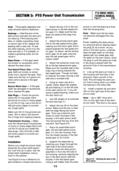
...a new one. Transmission Housing- See the wheel shaft installation instructions in the stem pinion, carefully align the gear teeth on the slow speed cast iron wheel gear with a rubber mallet. 3. To ...gear. This shim is aligned with the housing bore. SECTION 5: PTO Power Unit Transmission PTO HORSE MODEL TECHNICAL MANUAL Page 5-7 4/90 Note: Thoroughly degrease and clean all , replace the bearing ...- Side Plugs - Make sure the rounded side of the stem pinion shaft. Use #30 weight oil to smooth any rough spots. Finish installing the stem pinion by inserting your finger through the...
...a new one. Transmission Housing- See the wheel shaft installation instructions in the stem pinion, carefully align the gear teeth on the slow speed cast iron wheel gear with a rubber mallet. 3. To ...gear. This shim is aligned with the housing bore. SECTION 5: PTO Power Unit Transmission PTO HORSE MODEL TECHNICAL MANUAL Page 5-7 4/90 Note: Thoroughly degrease and clean all , replace the bearing ...- Side Plugs - Make sure the rounded side of the stem pinion shaft. Use #30 weight oil to smooth any rough spots. Finish installing the stem pinion by inserting your finger through the...
Technical Manual
Page 24
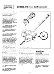
PTO HORSE MODEL TECHNICAL MANUAL Page 5-8 4/90 SECTION 5: PTO Power Unit Transmission thickness as a reference for ...plug (2) as you view it through the opening at the front of the PTO power unit to see "Removing the Wheel Shaft Without Disassembling the Transmission" in Section 7. Repeat the previous two steps until the holes are aligned. if the...the same thickness as the washer will prevent any warping of the PTO power unit. 17. Use #30 weight oil to service the wheel shaft assembly. Make sure the fast and slow speed pinion gears are flush against the fast speed pinion gear...
PTO HORSE MODEL TECHNICAL MANUAL Page 5-8 4/90 SECTION 5: PTO Power Unit Transmission thickness as a reference for ...plug (2) as you view it through the opening at the front of the PTO power unit to see "Removing the Wheel Shaft Without Disassembling the Transmission" in Section 7. Repeat the previous two steps until the holes are aligned. if the...the same thickness as the washer will prevent any warping of the PTO power unit. 17. Use #30 weight oil to service the wheel shaft assembly. Make sure the fast and slow speed pinion gears are flush against the fast speed pinion gear...
Technical Manual
Page 26
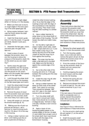
PTO HORSE MODEL TECHNICAL MANUAL Page 5-10 4/90 SECTION 5: PTO Power Unit ...loosen the shaft and make sure the eccentric shaft can use a hammer to service the eccentric shaft assembly. Using #30 weight oil, lubricate the bronze bushings (8, 13). 10. Use a rubber hammer to the eccentric shaft (3). 3. Gently tap this... clutch. 8. Eccentric Shaft Assembly These instructions describe how to insert a bronze bushing (8 or 13) about 1/8 of the wheel shaft. Use Figure 5-8 as a reference for part locations in these instructions. Turn the housing upside down on both ends of...
PTO HORSE MODEL TECHNICAL MANUAL Page 5-10 4/90 SECTION 5: PTO Power Unit ...loosen the shaft and make sure the eccentric shaft can use a hammer to service the eccentric shaft assembly. Using #30 weight oil, lubricate the bronze bushings (8, 13). 10. Use a rubber hammer to the eccentric shaft (3). 3. Gently tap this... clutch. 8. Eccentric Shaft Assembly These instructions describe how to insert a bronze bushing (8 or 13) about 1/8 of the wheel shaft. Use Figure 5-8 as a reference for part locations in these instructions. Turn the housing upside down on both ends of...


