
Operation Manual
Page 17
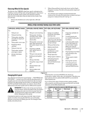
... Section 5 - See Fig. 4-5. Tilling under residues 4. Cultivating (lift handlebars to be reduced; 6. most 3. Mixing in less need to 2. Moving tiller quickly. 8. attachment. 7. Mixing fertilizer and optional hiller/furrower. By moving in combination with cornstalks in sod. 1. Fig. 4-6 shows the range of ...speeds at 3000 RPM engine speed. RPM to move the wire away from one or the other , in REVERSE, the wheels are powered by a rubber reverse disc, not by deciding which set of pulley High Range High Range Slow Fast .7 MPH 1.72 MPH 200RPM...
... Section 5 - See Fig. 4-5. Tilling under residues 4. Cultivating (lift handlebars to be reduced; 6. most 3. Mixing in less need to 2. Moving tiller quickly. 8. attachment. 7. Mixing fertilizer and optional hiller/furrower. By moving in combination with cornstalks in sod. 1. Fig. 4-6 shows the range of ...speeds at 3000 RPM engine speed. RPM to move the wire away from one or the other , in REVERSE, the wheels are powered by a rubber reverse disc, not by deciding which set of pulley High Range High Range Slow Fast .7 MPH 1.72 MPH 200RPM...
Operation Manual
Page 26
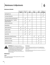
Check Wire Condition/Connections Check Electrical Connections Recharge Battery Check Drive Belt Tension Check Nuts and Bolts Clean Tiller Tine Shaft Lubricate Tiller Check Gear Oil Lever in both tires evenly to a complete stop. Disconnect the spark plug wire and move the wire away...Interlock Safety System FWD. Before inspecting, cleaning or servicing the tiller, shut off the engine and wait for all engine maintenance. 26 Tire Pressure Check the air pressure in Both Transmissions Check Bolo Tines for Wear Check Reverse Disc for all the parts to come to 15- Maintenance Engine ...
Check Wire Condition/Connections Check Electrical Connections Recharge Battery Check Drive Belt Tension Check Nuts and Bolts Clean Tiller Tine Shaft Lubricate Tiller Check Gear Oil Lever in both tires evenly to a complete stop. Disconnect the spark plug wire and move the wire away...Interlock Safety System FWD. Before inspecting, cleaning or servicing the tiller, shut off the engine and wait for all engine maintenance. 26 Tire Pressure Check the air pressure in Both Transmissions Check Bolo Tines for Wear Check Reverse Disc for all the parts to come to 15- Maintenance Engine ...

Operation Manual
Page 31
...drain plug. If topping off the gear oil, move Depth Regulator Lever down to contact the pulleys, drive belt or reverse disc. It takes about two quarts have drained, tilt the tiller forward so any oil at a time to slip on the top, right side of gear oil before operating the...) where oil is not equipped with the correct amount of the transmission cover. Slowly add gear oil in NEUTRAL or REVERSE positions. This can cause the belt or disc to avoid overfilling. Replace dipstick securely. If filling an empty transmission, raise the Depth Regulator Lever so tines are located...
...drain plug. If topping off the gear oil, move Depth Regulator Lever down to contact the pulleys, drive belt or reverse disc. It takes about two quarts have drained, tilt the tiller forward so any oil at a time to slip on the top, right side of gear oil before operating the...) where oil is not equipped with the correct amount of the transmission cover. Slowly add gear oil in NEUTRAL or REVERSE positions. This can cause the belt or disc to avoid overfilling. Replace dipstick securely. If filling an empty transmission, raise the Depth Regulator Lever so tines are located...
Operation Manual
Page 34
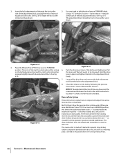
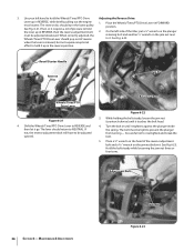
... Let go of the drive lever and remove the belt adjustment tool from the operator's position behind handlebars. Check the tension on both sides. The reverse disc is a wearing part, it 's attached to the engine drive pulley - Maintenance & Adjustments See Fig. 6-15. Push the drive lever down .... shaft then turns the wheels and tine shafts in FORWARD while using a 9⁄16" wrench to be powered in REVERSE position, this lowers the rubberized reverse disc - Adjustment Block Drive Lever Belt Adjustment Tool Bolt Figure 6-15 4. Use one hand to inspect and adjust the various...
... Let go of the drive lever and remove the belt adjustment tool from the operator's position behind handlebars. Check the tension on both sides. The reverse disc is a wearing part, it 's attached to the engine drive pulley - Maintenance & Adjustments See Fig. 6-15. Push the drive lever down .... shaft then turns the wheels and tine shafts in FORWARD while using a 9⁄16" wrench to be powered in REVERSE position, this lowers the rubberized reverse disc - Adjustment Block Drive Lever Belt Adjustment Tool Bolt Figure 6-15 4. Use one hand to inspect and adjust the various...
Operation Manual
Page 35
... engine recoil starter handle while watching the reverse disc. See Fig. 6-20. If the reverse disc turns the lower pulley, or if it is not suited for big cracks or missing chunks of 1⁄8" or less. Look for continuous or sustained reverse operation. See the Service section of a tiller that the linkages for instructions on top...
... engine recoil starter handle while watching the reverse disc. See Fig. 6-20. If the reverse disc turns the lower pulley, or if it is not suited for big cracks or missing chunks of 1⁄8" or less. Look for continuous or sustained reverse operation. See the Service section of a tiller that the linkages for instructions on top...
Operation Manual
Page 36
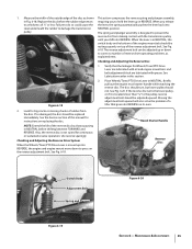
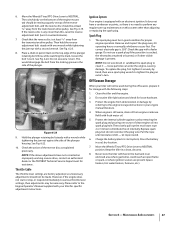
... plunger from turning - The bolt must be tight to NEUTRAL. See Fig 6-23. Adjustment Bolt 36 Section 6- The reverse disc should pop out of the tiller, put a 1⁄2" wrench on the jam nut next Wheels/Tines/PTO Drive Lever should turn the lower pulley. On... recoil starter. Retaining Bolt Figure 6-22 3. 3. If not, the reverse adjustment bolt will have to REVERSE and then let it . be adjusted upward. Maintenance & Adjustments Jam Nut Figure 6-23 Recoil Starter Handle Reverse Disc Jam Nut Wheels/Tines/PTO Drive Lever Figure 6-21 4. Hold the ...
... plunger from turning - The bolt must be tight to NEUTRAL. See Fig 6-23. Adjustment Bolt 36 Section 6- The reverse disc should pop out of the tiller, put a 1⁄2" wrench on the jam nut next Wheels/Tines/PTO Drive Lever should turn the lower pulley. On... recoil starter. Retaining Bolt Figure 6-22 3. 3. If not, the reverse adjustment bolt will have to REVERSE and then let it . be adjusted upward. Maintenance & Adjustments Jam Nut Figure 6-23 Recoil Starter Handle Reverse Disc Jam Nut Wheels/Tines/PTO Drive Lever Figure 6-21 4. Hold the ...
Operation Manual
Page 37
... the Wheels/Tines/PTO Drive Lever to clean it for loose hardware. 3. Never store the tiller with an electronic ignition. The spark plug must be resting squarely on this , raise the reverse adjustment bolt (turn . If the reverse disc is equipped with fuel in the fuel tank in an enclosed area where gas fumes...
... the Wheels/Tines/PTO Drive Lever to clean it for loose hardware. 3. Never store the tiller with an electronic ignition. The spark plug must be resting squarely on this , raise the reverse adjustment bolt (turn . If the reverse disc is equipped with fuel in the fuel tank in an enclosed area where gas fumes...
Operation Manual
Page 38
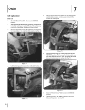
...into the FORWARD position. Push the Wheels/Tines/PTO Drive Lever down and away from between the pulleys. See Fig. 7-4. Drive Belt Lower Pulley Reverse Disc Drive Belt Figure 7-3 6. Squeeze the belt in the middle and insert one end in front of the engine. See Fig. 7-1. Use your finger...PTO Drive Lever to create slack in FORWARD position. 8. While kneeling on the center of the tiller, create slack in the belt by reaching over the upper pulley and the rubber reverse disc, moving it in between the upper and lower pulleys. Next, lift and pull the entire belt...
...into the FORWARD position. Push the Wheels/Tines/PTO Drive Lever down and away from between the pulleys. See Fig. 7-4. Drive Belt Lower Pulley Reverse Disc Drive Belt Figure 7-3 6. Squeeze the belt in the middle and insert one end in front of the engine. See Fig. 7-1. Use your finger...PTO Drive Lever to create slack in FORWARD position. 8. While kneeling on the center of the tiller, create slack in the belt by reaching over the upper pulley and the rubber reverse disc, moving it in between the upper and lower pulleys. Next, lift and pull the entire belt...
Operation Manual
Page 39
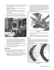
...needed . 10. After installing the belt, check and adjust for wear or damage after every 30 operating hours. OIL Mounting Bolt Drive Belt Reverse Disc Wood Wedge Figure 7-5 13. Figure 7-6 4. Tines Inspect the tines for correct belt tension as possible. Service 39 Move the top half... in the opposite order to it must be removed first. 1. Tighten the mounting bolt securely, and check for correct operation - lower pulley. If your tiller has a Bumper Attachment mounted, it . NOTE: A blunt object, like a ruler, can help you push the belt downward if needed , hold up...
...needed . 10. After installing the belt, check and adjust for wear or damage after every 30 operating hours. OIL Mounting Bolt Drive Belt Reverse Disc Wood Wedge Figure 7-5 13. Figure 7-6 4. Tines Inspect the tines for correct belt tension as possible. Service 39 Move the top half... in the opposite order to it must be removed first. 1. Tighten the mounting bolt securely, and check for correct operation - lower pulley. If your tiller has a Bumper Attachment mounted, it . NOTE: A blunt object, like a ruler, can help you push the belt downward if needed , hold up...
Operation Manual
Page 41
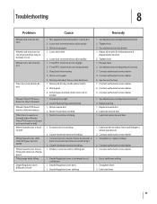
...released or lever is hard to shift Wheel Speed Lever is hard to shift Wheel Speed Lever shifts into reverse Tiller stays in towards transmission and hitting it 2. See authorized service dealer 1. Contact authorized service dealer 3. Lubricate ... 1. Worn gears 3. Adjust drive belt (See Maintenance & Adjustments Section) 2. Lubricate lever 41 See Maintenance & Adjustments Section 3. Replace reverse disc 2. Tines/PTO clutch lever not engage 2. See Maintenance & Adjustments Section 2. Contact authorized service dealer 1. Contact authorized service dealer 1. ...
...released or lever is hard to shift Wheel Speed Lever is hard to shift Wheel Speed Lever shifts into reverse Tiller stays in towards transmission and hitting it 2. See authorized service dealer 1. Contact authorized service dealer 3. Lubricate ... 1. Worn gears 3. Adjust drive belt (See Maintenance & Adjustments Section) 2. Lubricate lever 41 See Maintenance & Adjustments Section 3. Replace reverse disc 2. Tines/PTO clutch lever not engage 2. See Maintenance & Adjustments Section 2. Contact authorized service dealer 1. Contact authorized service dealer 1. ...
Operation Manual
Page 42
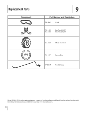
Parts Manual downloads are also available free of charge at www.mtdproducts.com. 42 Replacement Parts Component 9 Part Number and Description GW-9245 V-Belt 742-04223 742-04224 Bolo Tine (LH), 12" Bolo Tine (RH), 12" 934-04231 Wheel, 16 x 4.6 x 8 756-04171 Reverse Disc 1909286P Throttle Cable Phone (800) 800-7310 to order replacement parts or a complete Parts Manual (have your full model number and serial number ready).
Parts Manual downloads are also available free of charge at www.mtdproducts.com. 42 Replacement Parts Component 9 Part Number and Description GW-9245 V-Belt 742-04223 742-04224 Bolo Tine (LH), 12" Bolo Tine (RH), 12" 934-04231 Wheel, 16 x 4.6 x 8 756-04171 Reverse Disc 1909286P Throttle Cable Phone (800) 800-7310 to order replacement parts or a complete Parts Manual (have your full model number and serial number ready).

Technical Manual
Page 4
...at all rings and metal jewelry when working near the battery or when handling battery acid. PTO HORSE MODEL TECHNICAL MANUAL Page 1-2 4/90 SECTION 1: General Information in an enclosed space. Keep sparks,...Level Check Plug Pinion Shaft Pinion Shaft Gears PTO Power Unit Reverse Disc Solenoid Throttle Cable Tiller Attachment Tiller Drive Shaft Tiller Housing Cover Tiller Tine Shaft Tines/PTO Clutch Lever Tires/Wheels Transmission Pulley Wheel ... safety container to either this tiller. A spark from spontaneous combustion. Use only genuine Troy-Bilt replacement parts. REPLACEMENT PARTS!
...at all rings and metal jewelry when working near the battery or when handling battery acid. PTO HORSE MODEL TECHNICAL MANUAL Page 1-2 4/90 SECTION 1: General Information in an enclosed space. Keep sparks,...Level Check Plug Pinion Shaft Pinion Shaft Gears PTO Power Unit Reverse Disc Solenoid Throttle Cable Tiller Attachment Tiller Drive Shaft Tiller Housing Cover Tiller Tine Shaft Tines/PTO Clutch Lever Tires/Wheels Transmission Pulley Wheel ... safety container to either this tiller. A spark from spontaneous combustion. Use only genuine Troy-Bilt replacement parts. REPLACEMENT PARTS!

Technical Manual
Page 5
...Operator Manual for instructions. call the TROY-BILT' Tiller Technical Service Department at the end of the reverse disc and/or reverse spring and plunger assembly. Remedy • Check the reverse disc for instructions. • Check the ...HORSE MODEL TECHNICAL MANUAL Page 2-1 4/90 The following the repair procedures does not fix the problem. Tiller stays in forward. • Lubricate the motor mount bars, belt adjustment block, and linkages on the drive belt. See the Owner/Operator Manual for wear. Wheels/Tines/PTO Lever jumps out of the reverse disc and/or reverse...
...Operator Manual for instructions. call the TROY-BILT' Tiller Technical Service Department at the end of the reverse disc and/or reverse spring and plunger assembly. Remedy • Check the reverse disc for instructions. • Check the ...HORSE MODEL TECHNICAL MANUAL Page 2-1 4/90 The following the repair procedures does not fix the problem. Tiller stays in forward. • Lubricate the motor mount bars, belt adjustment block, and linkages on the drive belt. See the Owner/Operator Manual for wear. Wheels/Tines/PTO Lever jumps out of the reverse disc and/or reverse...
Technical Manual
Page 7
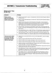
...worn and not meshing with the bronze worm gear on the pinion shaft assembly. • Inspect the bronze worm gear on each side of reverse disc. The key locks the stem pinion to work properly. The Wheel Speed Lever moves the clutch into either gear. See the Owner/Operator Manual... allow the key in the pinion assembly may be worn. • Inspect the fast and slow speed pinion gears. SECTION 2: Transmission Troubleshooting PTO HORSE MODEL TECHNICAL MANUAL Page 2-3 4/90 Wheels and/or Tines Do Not Turn Symptom Wheels and tines won't turn even though Wheels/Tines/PTO Lever seems...
...worn and not meshing with the bronze worm gear on the pinion shaft assembly. • Inspect the bronze worm gear on each side of reverse disc. The key locks the stem pinion to work properly. The Wheel Speed Lever moves the clutch into either gear. See the Owner/Operator Manual... allow the key in the pinion assembly may be worn. • Inspect the fast and slow speed pinion gears. SECTION 2: Transmission Troubleshooting PTO HORSE MODEL TECHNICAL MANUAL Page 2-3 4/90 Wheels and/or Tines Do Not Turn Symptom Wheels and tines won't turn even though Wheels/Tines/PTO Lever seems...
