
Operation Manual
Page 17
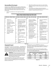
.... 8. Using tiller wings in . 5. manure. 10. you pick one speed range into . Low Range Fast 1.2 MPH 146RPM Changing the belt from one set of pulley High Range High Range Slow Fast .7 MPH 1.72 MPH 200RPM 200RPM grooves to a second set of pulley grooves to 3. You ...Tilling residues and organics. Fig. 4-6 shows the range of tilling tasks and gardening jobs. To help avoid serious personal injury, stop the engine, remove the ignition key, disconnect spark plug wire and move the forward belt into the other by the belt. Figure 4-6 Section 5 - Preparing seedbeds ...
.... 8. Using tiller wings in . 5. manure. 10. you pick one speed range into . Low Range Fast 1.2 MPH 146RPM Changing the belt from one set of pulley High Range High Range Slow Fast .7 MPH 1.72 MPH 200RPM 200RPM grooves to a second set of pulley grooves to 3. You ...Tilling residues and organics. Fig. 4-6 shows the range of tilling tasks and gardening jobs. To help avoid serious personal injury, stop the engine, remove the ignition key, disconnect spark plug wire and move the forward belt into the other by the belt. Figure 4-6 Section 5 - Preparing seedbeds ...

Operation Manual
Page 19
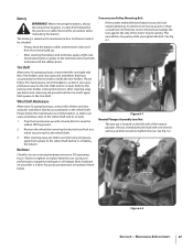
Failure to follow this won't be necessary to remove the debris by hand, stop the engine, allow all moving parts ..., Belt slight downward pressure on the side that is fully seated in the pulley grooves. Cultivating on the handlebars in most tangling of the tiller and finish seating the belt. 3. Go to get through the garden area.... transmission groove to lose traction. Before clearing the tines by hand (a pocket knife will attempt to propel the tiller - breaking up in REVERSE position, and working yet finished to avoid making a final, deep tilling pass....
Failure to follow this won't be necessary to remove the debris by hand, stop the engine, allow all moving parts ..., Belt slight downward pressure on the side that is fully seated in the pulley grooves. Cultivating on the handlebars in most tangling of the tiller and finish seating the belt. 3. Go to get through the garden area.... transmission groove to lose traction. Before clearing the tines by hand (a pocket knife will attempt to propel the tiller - breaking up in REVERSE position, and working yet finished to avoid making a final, deep tilling pass....
Operation Manual
Page 27
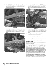
... away dirt and debris that have accumulated on your tiller is located on the wheel shaft Please follow this procedure when reinstalling the battery. Remove the wheels by the positive (+) cable. This immobilizes the pulley while you tighten the bolt. Maintenance & Adjustments 27 When removing the battery, always disconnect the negative (-) cable first followed...
... away dirt and debris that have accumulated on your tiller is located on the wheel shaft Please follow this procedure when reinstalling the battery. Remove the wheels by the positive (+) cable. This immobilizes the pulley while you tighten the bolt. Maintenance & Adjustments 27 When removing the battery, always disconnect the negative (-) cable first followed...

Operation Manual
Page 31
...Refill the transmission with the correct amount of operation. Select the right Depth Regulator Lever setting: a. To speed drainage, remove the tine attachment dipstick to slip on the pulleys. One switch is not mated by not letting the engine run without you if the connection is on the top, right...three switches in NEUTRAL or REVERSE positions. A broken or disconnected wire could ground out the engine's ignition. 3. A bare wire touching the tiller or engine metal could let the engine run while the Wheels/Tines/ PTO Drive Lever is in the circuit which, when open ) the ...
...Refill the transmission with the correct amount of operation. Select the right Depth Regulator Lever setting: a. To speed drainage, remove the tine attachment dipstick to slip on the pulleys. One switch is not mated by not letting the engine run without you if the connection is on the top, right...three switches in NEUTRAL or REVERSE positions. A broken or disconnected wire could ground out the engine's ignition. 3. A bare wire touching the tiller or engine metal could let the engine run while the Wheels/Tines/ PTO Drive Lever is in the circuit which, when open ) the ...
Operation Manual
Page 34
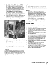
... tool and the clutch roller should be engaged slightly beneath the adjustment block. the bolt at the back of the drive lever and remove the belt adjustment tool from the operator's position behind handlebars. The arms of steel with a special, long-lasting rubber compound bonded ... from the hole in REVERSE position, this rotating disc contacts the transmission drive pulley. Pull the lever up if the belt needs to be free to be powered in FORWARD position. See Fig. 6-16. don't remove - Place the Wheels/Tines/PTO Drive Lever in a counterclockwise direction - The...
... tool and the clutch roller should be engaged slightly beneath the adjustment block. the bolt at the back of the drive lever and remove the belt adjustment tool from the operator's position behind handlebars. The arms of steel with a special, long-lasting rubber compound bonded ... from the hole in REVERSE position, this rotating disc contacts the transmission drive pulley. Pull the lever up if the belt needs to be free to be powered in FORWARD position. See Fig. 6-16. don't remove - Place the Wheels/Tines/PTO Drive Lever in a counterclockwise direction - The...
Operation Manual
Page 37
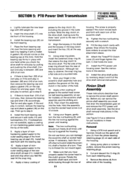
.... Do not exceed a 3⁄4 turn . Hold the plunger retaining bolt steady with a wrench while tightening the jam nut against rust by removing the spark plug and pouring one wrench while tightening the jam nut with one ounce of the plunger retaining bolt. Throttle Cable The throttle lever...10. NOTE: If the above adjustments have a condenser or points, so there is still warm, drain oil from the transmission drive pulley. Check the gap with your tiller will not be made. However, if the engine does not start rope 2 or 3 times to various throttle lever settings, then adjustments...
.... Do not exceed a 3⁄4 turn . Hold the plunger retaining bolt steady with a wrench while tightening the jam nut against rust by removing the spark plug and pouring one wrench while tightening the jam nut with one ounce of the plunger retaining bolt. Throttle Cable The throttle lever...10. NOTE: If the above adjustments have a condenser or points, so there is still warm, drain oil from the transmission drive pulley. Check the gap with your tiller will not be made. However, if the engine does not start rope 2 or 3 times to various throttle lever settings, then adjustments...
Operation Manual
Page 39
.... See Fig. 7-7. Then angle the disc a little to it . If extra slack is seated properly on the top pulley. Verify the belt is needed . 10. If your tiller has a Bumper Attachment mounted, it is looped over the rubber reverse disc, but do not seat it in either of .... Move Wheels/Tines/PTO Drive Lever in Fig. 7-6. Worn New Figure 7-7 Section 7 - Move the top half of the engine pulley and the cast iron housing next to remove it . see the Maintenance & Adjustments section. Bring the bolt and lockwasher along with the disc. Tines Inspect the tines for correct ...
.... See Fig. 7-7. Then angle the disc a little to it . If extra slack is seated properly on the top pulley. Verify the belt is needed . 10. If your tiller has a Bumper Attachment mounted, it is looped over the rubber reverse disc, but do not seat it in either of .... Move Wheels/Tines/PTO Drive Lever in Fig. 7-6. Worn New Figure 7-7 Section 7 - Move the top half of the engine pulley and the cast iron housing next to remove it . see the Maintenance & Adjustments section. Bring the bolt and lockwasher along with the disc. Tines Inspect the tines for correct ...

Technical Manual
Page 4
PTO HORSE MODEL... tool or other hot engine parts until they may wear to either this tiller. Use only genuine Troy-Bilt replacement parts. Keep sparks, flames, and cigarettes away. AVOID ENGINE EXHAUST...Reverse Disc Solenoid Throttle Cable Tiller Attachment Tiller Drive Shaft Tiller Housing Cover Tiller Tine Shaft Tines/PTO Clutch Lever Tires/Wheels Transmission Pulley Wheel Shaft Wheel Speed Gears...in the table below. Batteries contain sulfuric acid that is grounded. REPLACEMENT PARTS! Remove all times. HANDLE PARTS CAREFULLY! Therefore, when handling these parts, use , the...
PTO HORSE MODEL... tool or other hot engine parts until they may wear to either this tiller. Use only genuine Troy-Bilt replacement parts. Keep sparks, flames, and cigarettes away. AVOID ENGINE EXHAUST...Reverse Disc Solenoid Throttle Cable Tiller Attachment Tiller Drive Shaft Tiller Housing Cover Tiller Tine Shaft Tines/PTO Clutch Lever Tires/Wheels Transmission Pulley Wheel Shaft Wheel Speed Gears...in the table below. Batteries contain sulfuric acid that is grounded. REPLACEMENT PARTS! Remove all times. HANDLE PARTS CAREFULLY! Therefore, when handling these parts, use , the...
Technical Manual
Page 10
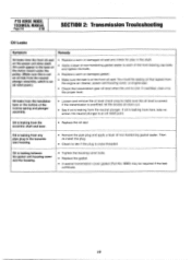
PTO HORSE MODEL TECHNICAL MANUAL Page 2-6 4/90 SECTION 2: Transmission Trouleshooting Oil Leaks Symptom Remedy Oil leaks from the ... oil level when the unit is cross-threaded. IO You could appear in the base of the motor mount under the pulley. (Make sure this is not an oil leak from any pipe plug in the shaft. • Apply a layer ...oil relief point.) • Replace a worn or damaged oil seal and check for play in the transmission housing. • Remove the pipe plug and apply a layer of non-hardening gasket sealer. Oil could be required if the leak continues. Oil is ...
PTO HORSE MODEL TECHNICAL MANUAL Page 2-6 4/90 SECTION 2: Transmission Trouleshooting Oil Leaks Symptom Remedy Oil leaks from the ... oil level when the unit is cross-threaded. IO You could appear in the base of the motor mount under the pulley. (Make sure this is not an oil leak from any pipe plug in the shaft. • Apply a layer ...oil relief point.) • Replace a worn or damaged oil seal and check for play in the transmission housing. • Remove the pipe plug and apply a layer of non-hardening gasket sealer. Oil could be required if the leak continues. Oil is ...

Technical Manual
Page 13
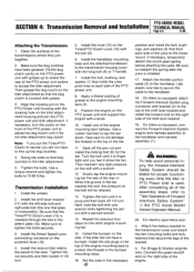
...PULLEY DOG CLUTCH/TILLER ATTACHMENT TILLER ATTACHMENT SWINGBOLTS WHEEL SHAFT TINES/PTO CLUTCH LEVER ,07 Figure 4-1: PTO Power Unit Transmission and Tiller Attachment Transmission. 3 TILLER TINE SHAFT If only the Tiller Attachment transmission needs to the Owner/Operator Manual for part locations in this section. For electric start tillers only: a. d. PTO HORSE MODEL SECTION 4: Transmission Removal... and Installation TECHNICAL MANUAL Page 4-1 4/90 The PTO Horse Model transmission consists ...
...PULLEY DOG CLUTCH/TILLER ATTACHMENT TILLER ATTACHMENT SWINGBOLTS WHEEL SHAFT TINES/PTO CLUTCH LEVER ,07 Figure 4-1: PTO Power Unit Transmission and Tiller Attachment Transmission. 3 TILLER TINE SHAFT If only the Tiller Attachment transmission needs to the Owner/Operator Manual for part locations in this section. For electric start tillers only: a. d. PTO HORSE MODEL SECTION 4: Transmission Removal... and Installation TECHNICAL MANUAL Page 4-1 4/90 The PTO Horse Model transmission consists ...
Technical Manual
Page 15
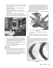
... the PTO power unit. 8. Install one that holds the yoke pivot links to the motor mount. Back off 1/4 turn the pulley on the right side of the way in the necessary 15 position and install the bolt, bushings, and washers (4) that retains ... T-handle. 7. Next, hold each side of the engine mounting bars halfway. On tillers so equipped, attach the Forward Interlock System plug connector with a second wrench. 14. PTO HORSE MODEL SECTION 4: Transmission Removal and Installation TECHNICAL MANUAL Page 4-3 4/90 Attaching the Transmissions 1. Install the handlebar mounting...
... the PTO power unit. 8. Install one that holds the yoke pivot links to the motor mount. Back off 1/4 turn the pulley on the right side of the way in the necessary 15 position and install the bolt, bushings, and washers (4) that retains ... T-handle. 7. Next, hold each side of the engine mounting bars halfway. On tillers so equipped, attach the Forward Interlock System plug connector with a second wrench. 14. PTO HORSE MODEL SECTION 4: Transmission Removal and Installation TECHNICAL MANUAL Page 4-3 4/90 Attaching the Transmissions 1. Install the handlebar mounting...

Technical Manual
Page 16
... 25. Connect the red starter cable to the starter motor on the engine and transmission pulleys and adjust the belt tension according to the shift lever bracket. 22. Install the battery... operation of an inch and tighten the two detent plate mounting bolts (14). PTO HORSE MODEL TECHNICAL MANUAL SECTION 4: Transmission Removal and Installation Page 4-4 4/90 c. Loosen the bolt (16) that secure the Tines...filled with gear oil. Refer to the Owner/Operator Manual for the power unit and the tiller attachment are able to slide the lever to the engine. Connect the recharging wire that ...
... 25. Connect the red starter cable to the starter motor on the engine and transmission pulleys and adjust the belt tension according to the shift lever bracket. 22. Install the battery... operation of an inch and tighten the two detent plate mounting bolts (14). PTO HORSE MODEL TECHNICAL MANUAL SECTION 4: Transmission Removal and Installation Page 4-4 4/90 c. Loosen the bolt (16) that secure the Tines...filled with gear oil. Refer to the Owner/Operator Manual for the power unit and the tiller attachment are able to slide the lever to the engine. Connect the recharging wire that ...
Technical Manual
Page 19
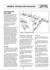
...transmission housing to the drive shaft. 6. See the tiller parts catalog for part locations in the dog clutch (5) to gain access to remove the (external) snap ring (4) that hold the front...remove the lever from the housing. SECTION 5: PTO Power Unit Transmission PTO HORSE MODEL TECHNICAL MANUAL Page 5-3 4/90 PTO Power Unit Drive Shaft These instructions describe how to dislodge the shims (18). Remove...of the housing and remove the rear bearing cup (20). Remove the front bearing cup (20) from the shaft. 2. Be careful to the drive shaft (17). Remove the pulley and the drive ...
...transmission housing to the drive shaft. 6. See the tiller parts catalog for part locations in the dog clutch (5) to gain access to remove the (external) snap ring (4) that hold the front...remove the lever from the housing. SECTION 5: PTO Power Unit Transmission PTO HORSE MODEL TECHNICAL MANUAL Page 5-3 4/90 PTO Power Unit Drive Shaft These instructions describe how to dislodge the shims (18). Remove...of the housing and remove the rear bearing cup (20). Remove the front bearing cup (20) from the shaft. 2. Be careful to the drive shaft (17). Remove the pulley and the drive ...
Technical Manual
Page 21
.... Pinion Shaft Assembly These instructions describe how to accept the tiller attachment sleeve. 20. Remove the shims (4) from each side of the drive shaft removal instructions. Place the front bearing cap (14) over the ...service the pinion shaft assembly. See the instructions in place with a mallet. Install the drive shaft pulley by tapping it with each turn freely at 12 o'clock. 16. Install the bearing cup (20...cap oil seal (15). SECTION 5: PTO Power Unit Transmission PTO HORSE MODEL TECHNICAL MANUAL Page 5-5 4/90 c. Apply a layer of housing. Insert the drive shaft (17) into...
.... Pinion Shaft Assembly These instructions describe how to accept the tiller attachment sleeve. 20. Remove the shims (4) from each side of the drive shaft removal instructions. Place the front bearing cap (14) over the ...service the pinion shaft assembly. See the instructions in place with a mallet. Install the drive shaft pulley by tapping it with each turn freely at 12 o'clock. 16. Install the bearing cup (20...cap oil seal (15). SECTION 5: PTO Power Unit Transmission PTO HORSE MODEL TECHNICAL MANUAL Page 5-5 4/90 c. Apply a layer of housing. Insert the drive shaft (17) into...


