Operation Manual
Page 11
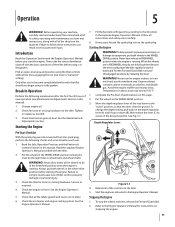
...the ground. When the wheels are in wheel hubs and wheel shaft). See Fig, 5-1. Tighten or replace as required. 4. Check transmission gear oil level. See the Maintenance & Adjustments section. Service as needed. 3. Check the air cleaner and engine cooling system. To change the depth...engine muffler and nearby areas. Start the engine as instructed in an enclosed, poorly ventilated area. Operation 5 WARNING! Change engine oil. 2. Check the engine oil level. See the Engine Operator's Manual. 5. Never have wheels in this page. 2. Find an open, level area and ...
...the ground. When the wheels are in wheel hubs and wheel shaft). See Fig, 5-1. Tighten or replace as required. 4. Check transmission gear oil level. See the Maintenance & Adjustments section. Service as needed. 3. Check the air cleaner and engine cooling system. To change the depth...engine muffler and nearby areas. Start the engine as instructed in an enclosed, poorly ventilated area. Operation 5 WARNING! Change engine oil. 2. Check the engine oil level. See the Engine Operator's Manual. 5. Never have wheels in this page. 2. Find an open, level area and ...
Operation Manual
Page 15
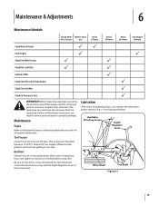
... away from pulling to one side. The air pressure should be between 15-20 PSI. Lubrication After every 10 operating hours, oil or grease the lubrication points shown in both tires equally inflated to the Engine Operator's Manual packed with your tiller for all engine... hours use Every 5 Hours Every 10 Hours Every 30 Hours See Engine Manual Check Motor Oil Level PP Clean Engine P P Check Drive Belt Tension P P Check Nuts and Bolts P P Lubricate Tiller P Check Gear Oil Level in Transmission P Check Tines for Wear P Check Air Pressure in serious personal injury ...
... away from pulling to one side. The air pressure should be between 15-20 PSI. Lubrication After every 10 operating hours, oil or grease the lubrication points shown in both tires equally inflated to the Engine Operator's Manual packed with your tiller for all engine... hours use Every 5 Hours Every 10 Hours Every 30 Hours See Engine Manual Check Motor Oil Level PP Clean Engine P P Check Drive Belt Tension P P Check Nuts and Bolts P P Lubricate Tiller P Check Gear Oil Level in Transmission P Check Tines for Wear P Check Air Pressure in serious personal injury ...
Operation Manual
Page 16
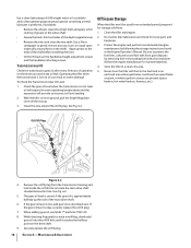
Apply grease to avoid overfilling, slowly add gear oil into the oil fill hole until it for storage as described next. Transmission Gear Oil Check the transmission gear oil after every 30 hours of the main drive shaft. 6. Check the gear oil level when the transmission is low, add gear oil as follows: 1. See Fig. 6-2. ... open flame or spark, or where ignition sources are present (space heaters, hot water heaters, furnaces, etc.). The gear oil level is correct if the gear oil is low on level ground, pull the Depth Regulator Lever all the way up the side of operation or whenever you...
Apply grease to avoid overfilling, slowly add gear oil into the oil fill hole until it for storage as described next. Transmission Gear Oil Check the transmission gear oil after every 30 hours of the main drive shaft. 6. Check the gear oil level when the transmission is low, add gear oil as follows: 1. See Fig. 6-2. ... open flame or spark, or where ignition sources are present (space heaters, hot water heaters, furnaces, etc.). The gear oil level is correct if the gear oil is low on level ground, pull the Depth Regulator Lever all the way up the side of operation or whenever you...
Operation Manual
Page 17
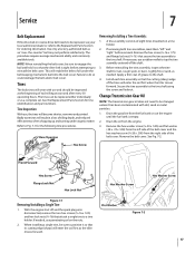
... assembly consists of the belt cover. Before reinstalling the tine assembly, inspect the tine shaft for tine identification and part numbers. Drain the oil from the right side of eight tines mounted on the nuts. 2. Remove the belt cover. With the engine shut off the shaft. ...before attempting to a tine holder. See Fig. 7-2. See the Replacement Parts Section for rust, rough spots or burrs. Change Transmission Gear Oil NOTE: The transmission gear oil does not need to be changed unless it so that the cutting (sharp) edge of the tines will enter the soil first ...
... assembly consists of the belt cover. Before reinstalling the tine assembly, inspect the tine shaft for tine identification and part numbers. Drain the oil from the right side of eight tines mounted on the nuts. 2. Remove the belt cover. With the engine shut off the shaft. ...before attempting to a tine holder. See Fig. 7-2. See the Replacement Parts Section for rust, rough spots or burrs. Change Transmission Gear Oil NOTE: The transmission gear oil does not need to be changed unless it so that the cutting (sharp) edge of the tines will enter the soil first ...
Operation Manual
Page 18
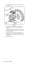
...the transmission cover to drain through the top of the transmission. 7. Reinstall the wheel and reinstall the transmission cover. 8. Service Refill the engine with motor oil and replenish the fuel tank with gasoline. 9. 4. Remove all dirt and clean the area around the transmission cover. Hex Screw Transmission Cover Transmission Housing ... Synthetic 75W 140. Reinstall the belt cover. 18 Section 7- See Fig. 7-3 6. See Fig. 7-3. Remove the left -side wheel shaft into a drain pan and allow the gear oil to the drive shaft and remove the cover. Tilt the left -side wheel.
...the transmission cover to drain through the top of the transmission. 7. Reinstall the wheel and reinstall the transmission cover. 8. Service Refill the engine with motor oil and replenish the fuel tank with gasoline. 9. 4. Remove all dirt and clean the area around the transmission cover. Hex Screw Transmission Cover Transmission Housing ... Synthetic 75W 140. Reinstall the belt cover. 18 Section 7- See Fig. 7-3 6. See Fig. 7-3. Remove the left -side wheel shaft into a drain pan and allow the gear oil to the drive shaft and remove the cover. Tilt the left -side wheel.
Service Manual
Page 16
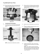
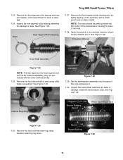
... Figure 7.2. Remove the front transmission cover and clean it. 7.4. Remove both shafts before assembly. Position a suitable oil drain pan directly in front of gear oil. 12 NOTE: When refilling an empty transmission, use approximately? Thoroughly clean the wheel shaft and tine shaft using ... assembly using contact cleaner and a shop rag. Troy-Bilt Small Frame Tillers 6.35. Hex Screws Wheel Shaft Front Transmission Cover E-Clips Figure 6.35 7. See Figure 7.1. See Figure 7.4. The Tuffy transmission will use only GL-4 gear oil having a viscosity of the wheel shaft using ...
... Figure 7.2. Remove the front transmission cover and clean it. 7.4. Remove both shafts before assembly. Position a suitable oil drain pan directly in front of gear oil. 12 NOTE: When refilling an empty transmission, use approximately? Thoroughly clean the wheel shaft and tine shaft using ... assembly using contact cleaner and a shop rag. Troy-Bilt Small Frame Tillers 6.35. Hex Screws Wheel Shaft Front Transmission Cover E-Clips Figure 6.35 7. See Figure 7.1. See Figure 7.4. The Tuffy transmission will use only GL-4 gear oil having a viscosity of the wheel shaft using ...
Service Manual
Page 17
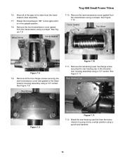
... hex flange screws securing the rear transmission cover and gasket to drain from the transmission using a scraper. Wheel Worm Cover Gasket Troy-Bilt Small Frame Tillers 7.10. Remove all of the gear oil to the transmission housing assembly using a scraper. Break the rear bearing cap free from the transmission using a 1/2" socket. Remove the front...
... hex flange screws securing the rear transmission cover and gasket to drain from the transmission using a scraper. Wheel Worm Cover Gasket Troy-Bilt Small Frame Tillers 7.10. Remove all of the gear oil to the transmission housing assembly using a scraper. Break the rear bearing cap free from the transmission using a 1/2" socket. Remove the front...
Service Manual
Page 19
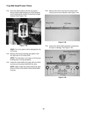
Troy-Bilt Small Frame Tillers 7.23. See Figure 7.24. See Figure 7.28. Internal Snap Ring Front Oil Seal Lubrication Cut A Way Bronze Bushing Spacer Wheel Shaft Worm Gear Figure 7.25 7.26. NOTE: The race should be ordered separately, they are purchased with a small punch and a rubber mallet. Remove the front drive shaft oil seal using medium...
Troy-Bilt Small Frame Tillers 7.23. See Figure 7.24. See Figure 7.28. Internal Snap Ring Front Oil Seal Lubrication Cut A Way Bronze Bushing Spacer Wheel Shaft Worm Gear Figure 7.25 7.26. NOTE: The race should be ordered separately, they are purchased with a small punch and a rubber mallet. Remove the front drive shaft oil seal using medium...

Service Manual
Page 20
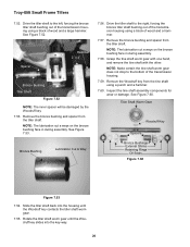
.... Remove the left sides of the wheel shaft using medium retaining ring pliers. Wheel Shaft Figure 7.33 7.34. Oil Seal Wheel Shaft Figure 7.32 NOTE: Make certain the transmission oil seal bores are not damaged during removal. Wheel Shaft Figure 7.34 External Shims 16 See Figure 7.33. Inspect the...and right retaining rings securing the wheel shaft in position using a small hook tool and a stick magnet. See Figure 7.32. Tiller Shaft Worm Gear Bronze Bushing Spacer Retaining Ring Figure 7.31 Spacer Bronze Bushing 7.32. Troy-Bilt Small Frame Tillers 7.31.
.... Remove the left sides of the wheel shaft using medium retaining ring pliers. Wheel Shaft Figure 7.33 7.34. Oil Seal Wheel Shaft Figure 7.32 NOTE: Make certain the transmission oil seal bores are not damaged during removal. Wheel Shaft Figure 7.34 External Shims 16 See Figure 7.33. Inspect the...and right retaining rings securing the wheel shaft in position using a small hook tool and a stick magnet. See Figure 7.32. Tiller Shaft Worm Gear Bronze Bushing Spacer Retaining Ring Figure 7.31 Spacer Bronze Bushing 7.32. Troy-Bilt Small Frame Tillers 7.31.
Service Manual
Page 22
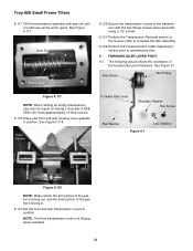
... a large hammer. Wheel Shaft Wheel Shaft Worm Gear Hi-Pro Key Bronze Bushings Internal Shims External Shims Retaining Rings Oil Seals Figure 7.46 18 Grasp the wheel shaft worm gear with one hand, and remove the wheel shaft with the other. Troy-Bilt Small Frame Tillers 7.42. See Figure 7.45.... See Figure 7.42. 7.45. Figure 7.45 7.46. Wheel Shaft Worm Gear Hammer 2" x 4" Hi-...
... a large hammer. Wheel Shaft Wheel Shaft Worm Gear Hi-Pro Key Bronze Bushings Internal Shims External Shims Retaining Rings Oil Seals Figure 7.46 18 Grasp the wheel shaft worm gear with one hand, and remove the wheel shaft with the other. Troy-Bilt Small Frame Tillers 7.42. See Figure 7.45.... See Figure 7.42. 7.45. Figure 7.45 7.46. Wheel Shaft Worm Gear Hammer 2" x 4" Hi-...
Service Manual
Page 24
... wear or damage. See Figure 7.60. Slide the tiller shaft back into the housing until the Woodruff key slides into the key-way. 20 Troy-Bilt Small Frame Tillers 7.52. Spacer Hammer 2" x 4" Bronze Bushing Tiller Shaft Figure 7.52 NOTE: The inner spacer will be damaged by the ...and remove the tine shaft with the other. Rotate the tiller shaft worm gear until the Woodruff key contacts the tiller shaft worm gear. 7.55. Tiller Shaft Worm Gear Woodruff Key Spacers Bronze Bushings External Shims Retaining Rings Oil Seals Figure 7.60 Figure 7.53 7.54. See Figure 7.52. Bronze ...
... wear or damage. See Figure 7.60. Slide the tiller shaft back into the housing until the Woodruff key slides into the key-way. 20 Troy-Bilt Small Frame Tillers 7.52. Spacer Hammer 2" x 4" Bronze Bushing Tiller Shaft Figure 7.52 NOTE: The inner spacer will be damaged by the ...and remove the tine shaft with the other. Rotate the tiller shaft worm gear until the Woodruff key contacts the tiller shaft worm gear. 7.55. Tiller Shaft Worm Gear Woodruff Key Spacers Bronze Bushings External Shims Retaining Rings Oil Seals Figure 7.60 Figure 7.53 7.54. See Figure 7.52. Bronze ...
Service Manual
Page 36
... the front and rear transmission covers in the reverse order to complete the tiller assembly. 8.122. Gear Oil Worm Gear 8.120. Hex Screw Idler Pulley Figure 8.117 NOTE: When refilling an empty transmission, use only GL-4 gear oil having a viscosity of the forward idler pivot hardware. Place new front and rear housing cover gaskets in... NOTE: Make certain the thin portion of the gasket is facing out, and the thick portion of the gasket is half way up the worm gears. Troy-Bilt Small Frame Tillers 8.117. Secure the transmission covers to operating the tiller. 9. See Figure 8.118.
... the front and rear transmission covers in the reverse order to complete the tiller assembly. 8.122. Gear Oil Worm Gear 8.120. Hex Screw Idler Pulley Figure 8.117 NOTE: When refilling an empty transmission, use only GL-4 gear oil having a viscosity of the forward idler pivot hardware. Place new front and rear housing cover gaskets in... NOTE: Make certain the thin portion of the gasket is facing out, and the thick portion of the gasket is half way up the worm gears. Troy-Bilt Small Frame Tillers 8.117. Secure the transmission covers to operating the tiller. 9. See Figure 8.118.


