Operation Manual
Page 1
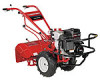
Safe Operation Practices • Set-Up • Operation • Maintenance • Service • Troubleshooting • Warranty Operator's Manual Rear-Tine Tiller - Printed In USA TROY-BILT LLC, P.O. BOX 361131 CLEVELAND, OHIO 44136-0019 Form No. 769-08675 (November 16, 2012) FAILURE TO COMPLY WITH THESE INSTRUCTIONS MAY RESULT IN PERSONAL INJURY. Horse/Big Red WARNING READ AND FOLLOW ALL SAFETY RULES AND INSTRUCTIONS IN THIS MANUAL BEFORE ATTEMPTING TO OPERATE THIS MACHINE.
Safe Operation Practices • Set-Up • Operation • Maintenance • Service • Troubleshooting • Warranty Operator's Manual Rear-Tine Tiller - Printed In USA TROY-BILT LLC, P.O. BOX 361131 CLEVELAND, OHIO 44136-0019 Form No. 769-08675 (November 16, 2012) FAILURE TO COMPLY WITH THESE INSTRUCTIONS MAY RESULT IN PERSONAL INJURY. Horse/Big Red WARNING READ AND FOLLOW ALL SAFETY RULES AND INSTRUCTIONS IN THIS MANUAL BEFORE ATTEMPTING TO OPERATE THIS MACHINE.
Technical Manual
Page 1
a°w $12.50 OTP0111-113ILT Technical Manual PTO HORSE Tiller Models 7 HP 8 HP GARDEN WAY INC.
a°w $12.50 OTP0111-113ILT Technical Manual PTO HORSE Tiller Models 7 HP 8 HP GARDEN WAY INC.
Technical Manual
Page 2
... Eccentric Shaft Assembly Removal Inspection Installation SECTION 6. Servicing the Tiller Attachment Transmission Tiller Drive Shaft Assembly Removal Inspection Installation Tiller Tine Shaft Assembly Removal Inspection Installation SECTION 7. Special Repairs ... Power Unit Drive Shaft 5-3 Removal 5-3 Inspection 5-4 Installation 5-4 Pinion Shaft Assembly 5-5 Removal 5-5 Inspection 5-6 Installation 5-7 SECTION 5. PTO HORSE MODEL TECHNICAL MANUAL 4/90 TABLE OF CONTENTS SECTION 1. (zeneral Information 1-1 Safety First 1-1 C- 4-k Reference Repair Index 1-2 SECTION 2. ...
... Eccentric Shaft Assembly Removal Inspection Installation SECTION 6. Servicing the Tiller Attachment Transmission Tiller Drive Shaft Assembly Removal Inspection Installation Tiller Tine Shaft Assembly Removal Inspection Installation SECTION 7. Special Repairs ... Power Unit Drive Shaft 5-3 Removal 5-3 Inspection 5-4 Installation 5-4 Pinion Shaft Assembly 5-5 Removal 5-5 Inspection 5-6 Installation 5-7 SECTION 5. PTO HORSE MODEL TECHNICAL MANUAL 4/90 TABLE OF CONTENTS SECTION 1. (zeneral Information 1-1 Safety First 1-1 C- 4-k Reference Repair Index 1-2 SECTION 2. ...
Technical Manual
Page 3
... gasoline cans or fuel tanks. SECTION 1: General Information PTO HORSE MODEL TECHNICAL MANUAL Page 1-1 4/90 • This manual provides transmission service information for the PTO HORSE Model TROY-BILT® Roto Tiller-Power Composter built by consulting the Service Repair Manuals available from... moving parts of the tiller or its safety message. If you would see references to operate...
... gasoline cans or fuel tanks. SECTION 1: General Information PTO HORSE MODEL TECHNICAL MANUAL Page 1-1 4/90 • This manual provides transmission service information for the PTO HORSE Model TROY-BILT® Roto Tiller-Power Composter built by consulting the Service Repair Manuals available from... moving parts of the tiller or its safety message. If you would see references to operate...

Technical Manual
Page 4
...terminals at all rings and metal jewelry when working near the battery or when handling battery acid. Use only genuine Troy-Bilt replacement parts. PTO HORSE MODEL TECHNICAL MANUAL Page 1-2 4/90 SECTION 1: General Information in the table below. approved covered metal safety container to...Transmission) Oil Level Check Plug Pinion Shaft Pinion Shaft Gears PTO Power Unit Reverse Disc Solenoid Throttle Cable Tiller Attachment Tiller Drive Shaft Tiller Housing Cover Tiller Tine Shaft Tines/PTO Clutch Lever Tires/Wheels Transmission Pulley Wheel Shaft Wheel Speed Gears Wheel Speed Lever ...
...terminals at all rings and metal jewelry when working near the battery or when handling battery acid. Use only genuine Troy-Bilt replacement parts. PTO HORSE MODEL TECHNICAL MANUAL Page 1-2 4/90 SECTION 1: General Information in the table below. approved covered metal safety container to...Transmission) Oil Level Check Plug Pinion Shaft Pinion Shaft Gears PTO Power Unit Reverse Disc Solenoid Throttle Cable Tiller Attachment Tiller Drive Shaft Tiller Housing Cover Tiller Tine Shaft Tines/PTO Clutch Lever Tires/Wheels Transmission Pulley Wheel Shaft Wheel Speed Gears Wheel Speed Lever ...

Technical Manual
Page 5
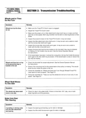
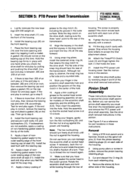
..., belt adjustment block, and linkages on the drive belt. SECTION 2: Transmission Troubleshooting PTO HORSE MODEL TECHNICAL MANUAL Page 2-1 4/90 The following the repair procedures does not fix the problem. Tiller stays in forward. • Lubricate the motor mount bars, belt adjustment block, and linkages.../PTO Lever is released. • Lubricate the motor mount bars, belt adjustment block, and linkages on the lever. call the TROY-BILT' Tiller Technical Service Department at the end of the engine by disconnecting the spark plug wire and keeping the wire away from the spark...
..., belt adjustment block, and linkages on the drive belt. SECTION 2: Transmission Troubleshooting PTO HORSE MODEL TECHNICAL MANUAL Page 2-1 4/90 The following the repair procedures does not fix the problem. Tiller stays in forward. • Lubricate the motor mount bars, belt adjustment block, and linkages.../PTO Lever is released. • Lubricate the motor mount bars, belt adjustment block, and linkages on the lever. call the TROY-BILT' Tiller Technical Service Department at the end of the engine by disconnecting the spark plug wire and keeping the wire away from the spark...
Technical Manual
Page 8
...slide lengthwise on their shafts. • Inspect the eccentric lever on top of the groove(s). Both dog clutches must be able to the tiller shaft may be broken. If the transmission is missing. This would allow the key inside the pulley to work properly." See Page 2-3....; If the transmission has been in place and that hold the tine holders to mesh with the bronze tiller shaft worm gear. • Inspect the bronze tiller drive shaft worm gear. PTO HORSE MODEL TECHNICAL MANUAL Page 2-4 4/90 SECTION 2: Transmission Troubleshooting Wheels and/or Tines Do Not Turn Symptom...
...slide lengthwise on their shafts. • Inspect the eccentric lever on top of the groove(s). Both dog clutches must be able to the tiller shaft may be broken. If the transmission is missing. This would allow the key inside the pulley to work properly." See Page 2-3....; If the transmission has been in place and that hold the tine holders to mesh with the bronze tiller shaft worm gear. • Inspect the bronze tiller drive shaft worm gear. PTO HORSE MODEL TECHNICAL MANUAL Page 2-4 4/90 SECTION 2: Transmission Troubleshooting Wheels and/or Tines Do Not Turn Symptom...
Technical Manual
Page 9
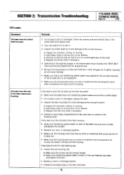
...filled with SAE 90 or SAE 140 gear oil. Check for a special seal. • Be sure the transmission is worn or damaged. Contact the TROY-BILT Technical Service Department for side-to seep out beteen the seal and the housing. If the leak is on an undamaged part of the shaft...to seep out between the seal and the housing. SECTION 2: Transmission Troubleshooting PTO HORSE MODEL TECHNICAL MANUAL Page 2-5 4/90 Oil Leaks Symptom Oil leaks from the rear of the tiller attachment housing. If the leak is on the tiller tine shaft: • Make sure the seals have non-hardening gasket sealer ...
...filled with SAE 90 or SAE 140 gear oil. Check for a special seal. • Be sure the transmission is worn or damaged. Contact the TROY-BILT Technical Service Department for side-to seep out beteen the seal and the housing. If the leak is on an undamaged part of the shaft...to seep out between the seal and the housing. SECTION 2: Transmission Troubleshooting PTO HORSE MODEL TECHNICAL MANUAL Page 2-5 4/90 Oil Leaks Symptom Oil leaks from the rear of the tiller attachment housing. If the leak is on the tiller tine shaft: • Make sure the seals have non-hardening gasket sealer ...

Technical Manual
Page 11
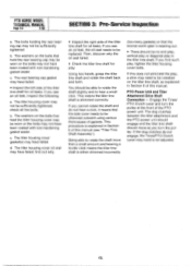
...additional problems that can be shimmed or that one or both of the following : • Inspect the area around one or both of the tiller attachment (see an oil leak, inspect the following : a. Wheel Shaft - See Figure 3-1. 0 OD O Figure 3-1: Pre-Disassembly Inspection ...your repair or maintenance procedure take a moment to be sufficiently tightened. b. d. If you see Figure 3-3). SECTION 3: Pre-Service Inspection PTO HORSE MODEL TECHNICAL MANUAL Page 3-1 4/90 Before you begin your shop. WARNING: When servicing the machine, prevent unintentional starting of the Wheel Shaft....
...additional problems that can be shimmed or that one or both of the following : • Inspect the area around one or both of the tiller attachment (see an oil leak, inspect the following : a. Wheel Shaft - See Figure 3-1. 0 OD O Figure 3-1: Pre-Disassembly Inspection ...your repair or maintenance procedure take a moment to be sufficiently tightened. b. d. If you see Figure 3-3). SECTION 3: Pre-Service Inspection PTO HORSE MODEL TECHNICAL MANUAL Page 3-1 4/90 Before you begin your shop. WARNING: When servicing the machine, prevent unintentional starting of the Wheel Shaft....
Technical Manual
Page 12
...shimmed correctly. b. PTO Power Unit and Tiller Attachment Drive Shaft Connection - Engage the Tines/ PTO Clutch Lever and turn the pulley. find such play : Using two hands, grasp the tiller tine shaft and rotate the shaft back and forth. PTO HORSE MODEL TECHNICAL MANUAL Page 3-2 4/90 SECTION... 3: Pre-Service Inspection a. The tiller housing cover oil seal may not be able to rotate the shaft ...
...shimmed correctly. b. PTO Power Unit and Tiller Attachment Drive Shaft Connection - Engage the Tines/ PTO Clutch Lever and turn the pulley. find such play : Using two hands, grasp the tiller tine shaft and rotate the shaft back and forth. PTO HORSE MODEL TECHNICAL MANUAL Page 3-2 4/90 SECTION... 3: Pre-Service Inspection a. The tiller housing cover oil seal may not be able to rotate the shaft ...

Technical Manual
Page 13
... 4/90 The PTO Horse Model transmission consists of the engine by disconnecting the spark plug wire and keeping the wire away from the spark plug. A WARNING: When servicing the machine, prevent unintentional starting of two separate transmission assemblies: the PTO Power Unit transmission and the Tiller Attachment transmission (see... are held together by following the instructions in the Owner/Operator Manual. Use Figure 4-2 as described in this section. Disconnect the red starter cable from the tiller as a complete assembly by a locking collar, a dowel pin and two swing-bolts. d.
... 4/90 The PTO Horse Model transmission consists of the engine by disconnecting the spark plug wire and keeping the wire away from the spark plug. A WARNING: When servicing the machine, prevent unintentional starting of two separate transmission assemblies: the PTO Power Unit transmission and the Tiller Attachment transmission (see... are held together by following the instructions in the Owner/Operator Manual. Use Figure 4-2 as described in this section. Disconnect the red starter cable from the tiller as a complete assembly by a locking collar, a dowel pin and two swing-bolts. d.
Technical Manual
Page 14
...Take care to the lever. Remove the bumper/guard attachment. Then remove the bolt from the tiller. 13. Lubricate both engine mounting bars. Remove the engine from each side. 9. Remove the ...11), one from the right side. Or, if the wheel is not attached. 8. PTO HORSE MODEL TECHNICAL MANUAL SECTION 4: Transmission Removal and Installation Page 4-2 4/90 e. Remove the two ...Removal and Installation. 11. After you remove the final engine mounting bar. 10. Or, remove the red plugs in Figure 4-1) that is necessary to the transmission cover and remove the bracket. 3. This ...
...Take care to the lever. Remove the bumper/guard attachment. Then remove the bolt from the tiller. 13. Lubricate both engine mounting bars. Remove the engine from each side. 9. Remove the ...11), one from the right side. Or, if the wheel is not attached. 8. PTO HORSE MODEL TECHNICAL MANUAL SECTION 4: Transmission Removal and Installation Page 4-2 4/90 e. Remove the two ...Removal and Installation. 11. After you remove the final engine mounting bar. 10. Or, remove the red plugs in Figure 4-1) that is necessary to the transmission cover and remove the bracket. 3. This ...
Technical Manual
Page 15
...hole on the PTO Power Unit housing with a block. 10. Next, hold each side of the PTO power unit. 8. If the tiller did not have a bumper, install the red plugs in the top of the engine mounting bars to protect the threads in the top of the yoke to the motor... equipped, connect the Forward Interlock System engine wire harness assembly to tap the bar down. Clean the surfaces of Forward Interlock Safety System" the PTO Horse Model Owner/Operator Manual. 20. Note: If you put the Tines/PTO Clutch in horizontally). Transmission Installation 1. Install the shift lever bracket (11) with...
...hole on the PTO Power Unit housing with a block. 10. Next, hold each side of the PTO power unit. 8. If the tiller did not have a bumper, install the red plugs in the top of the engine mounting bars to protect the threads in the top of the yoke to the motor... equipped, connect the Forward Interlock System engine wire harness assembly to tap the bar down. Clean the surfaces of Forward Interlock Safety System" the PTO Horse Model Owner/Operator Manual. 20. Note: If you put the Tines/PTO Clutch in horizontally). Transmission Installation 1. Install the shift lever bracket (11) with...

Technical Manual
Page 16
... DISENGAGE position. 25. Refer to the Owner/Operator Manual for the power unit and the tiller attachment are able to slide the lever to the eccentric shaft. 23. Check the operation... secure the Tines/PTO Clutch Lever detent plate (15) to the shaft. e. Connect the red starter cable to the starter motor on making final adjustments to the engine. Move the lever ...inside one of the housing against the lever until it into Forward, then Neutral and Reverse. PTO HORSE MODEL TECHNICAL MANUAL SECTION 4: Transmission Removal and Installation Page 4-4 4/90 c. Move the plate forward...
... DISENGAGE position. 25. Refer to the Owner/Operator Manual for the power unit and the tiller attachment are able to slide the lever to the eccentric shaft. 23. Check the operation... secure the Tines/PTO Clutch Lever detent plate (15) to the shaft. e. Connect the red starter cable to the starter motor on making final adjustments to the engine. Move the lever ...inside one of the housing against the lever until it into Forward, then Neutral and Reverse. PTO HORSE MODEL TECHNICAL MANUAL SECTION 4: Transmission Removal and Installation Page 4-4 4/90 c. Move the plate forward...

Technical Manual
Page 17
...rod swivel (see inset) (8) to the eccentric lever (9). 6. Remove the shift lever bracket. 5. SECTION 5: PTO Power Unit Transmission PTO HORSE MODEL TECHNICAL MANUAL Page 5-1 4/90 The following subsections explain how to service various items on the left side of the transmission housing. If the... sealer on a bench or other comfortable work area. 117 8. Discard the gasket (12). Then remove the knob. 2. Removal 1. Separate the tiller attachment from the spark plug. Remove the bolt (1) that holds the Tines/PTO Clutch Lever knob (2) to service the PTO power unit housing cover...
...rod swivel (see inset) (8) to the eccentric lever (9). 6. Remove the shift lever bracket. 5. SECTION 5: PTO Power Unit Transmission PTO HORSE MODEL TECHNICAL MANUAL Page 5-1 4/90 The following subsections explain how to service various items on the left side of the transmission housing. If the... sealer on a bench or other comfortable work area. 117 8. Discard the gasket (12). Then remove the knob. 2. Removal 1. Separate the tiller attachment from the spark plug. Remove the bolt (1) that holds the Tines/PTO Clutch Lever knob (2) to service the PTO power unit housing cover...
Technical Manual
Page 18
...1, 2 and 3. Plunger Bolt - Affix the gasket (12) to the PTO power unit and then reinstall the transmission assem- Reattach the tiller attachment to the cover. 2. Place the housing cover on the bottom of the neutral plunger and insert the neutral plunger into the neutral plunger....Section 4 for instructions on the bolt will sometimes free a frozen bolt) or if the plunger bolt (13) has snapped off . PTO HORSE MODEL TECHNICAL MANUAL Page 5-2 4/90 SECTION 5: PTO Power Unit Transmission Inspection These instructions describe how to lock it strike the neutral plunger. Inspect...
...1, 2 and 3. Plunger Bolt - Affix the gasket (12) to the PTO power unit and then reinstall the transmission assem- Reattach the tiller attachment to the cover. 2. Place the housing cover on the bottom of the neutral plunger and insert the neutral plunger into the neutral plunger....Section 4 for instructions on the bolt will sometimes free a frozen bolt) or if the plunger bolt (13) has snapped off . PTO HORSE MODEL TECHNICAL MANUAL Page 5-2 4/90 SECTION 5: PTO Power Unit Transmission Inspection These instructions describe how to lock it strike the neutral plunger. Inspect...
Technical Manual
Page 19
... Power Unit Housing Cover" in through the front of the transmission housing to its own part number and requires specific related parts. See the tiller parts catalog for removal instructions. Then remove the lever from the front bearing cap. 11. If it is excessively worn or damaged, or if... PTO power unit drive shaft. Also make sure you If you retrieve the drive shaft key (10). 5. SECTION 5: PTO Power Unit Transmission PTO HORSE MODEL TECHNICAL MANUAL Page 5-3 4/90 PTO Power Unit Drive Shaft These instructions describe how to dislodge the shims (18). Use snap ring pliers to ...
... Power Unit Housing Cover" in through the front of the transmission housing to its own part number and requires specific related parts. See the tiller parts catalog for removal instructions. Then remove the lever from the front bearing cap. 11. If it is excessively worn or damaged, or if... PTO power unit drive shaft. Also make sure you If you retrieve the drive shaft key (10). 5. SECTION 5: PTO Power Unit Transmission PTO HORSE MODEL TECHNICAL MANUAL Page 5-3 4/90 PTO Power Unit Drive Shaft These instructions describe how to dislodge the shims (18). Use snap ring pliers to ...
Technical Manual
Page 21
...remove the bearing cap and place a gasket (16) on the cap. Hold the assembly so that retains the dog clutch to accept the tiller attachment sleeve. 20. The screw is between .005 and .010 of the front bearing cap oil seal (15). Attach the Tines/PTO Clutch... Use Figure 5-4 as a reference for end play is between .005 and .010 of the housing. 6. SECTION 5: PTO Power Unit Transmission PTO HORSE MODEL TECHNICAL MANUAL Page 5-5 4/90 c. Tighten the hex nut/bushing securely with grease. Install the drive shaft pulley by tapping it with a mallet....
...remove the bearing cap and place a gasket (16) on the cap. Hold the assembly so that retains the dog clutch to accept the tiller attachment sleeve. 20. The screw is between .005 and .010 of the front bearing cap oil seal (15). Attach the Tines/PTO Clutch... Use Figure 5-4 as a reference for end play is between .005 and .010 of the housing. 6. SECTION 5: PTO Power Unit Transmission PTO HORSE MODEL TECHNICAL MANUAL Page 5-5 4/90 c. Tighten the hex nut/bushing securely with grease. Install the drive shaft pulley by tapping it with a mallet....
Technical Manual
Page 28
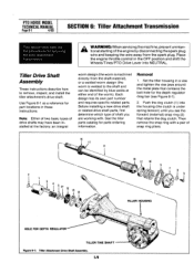
... (external) snap ring (2) that retains the dog clutch. Note: Either of two basic types of the worm). See the tiller parts catalog for servicing the tiller attachment transmission. Then remove the snap ring with . A WARNING: When servicing the machine, prevent unintentional starting of the engine ... tension) until you are working with a pair of shaft you see Figure 6-1). 2. Push the dog clutch (1) into NEUTRAL. PTO HORSE MODEL TECHNICAL MANUAL Page 6-1 4/90 SECTION 6: Tiller Attachment Transmission This section describes the the procedures for parts ordering information.
... (external) snap ring (2) that retains the dog clutch. Note: Either of two basic types of the worm). See the tiller parts catalog for servicing the tiller attachment transmission. Then remove the snap ring with . A WARNING: When servicing the machine, prevent unintentional starting of the engine ... tension) until you are working with a pair of shaft you see Figure 6-1). 2. Push the dog clutch (1) into NEUTRAL. PTO HORSE MODEL TECHNICAL MANUAL Page 6-1 4/90 SECTION 6: Tiller Attachment Transmission This section describes the the procedures for parts ordering information.
Technical Manual
Page 29
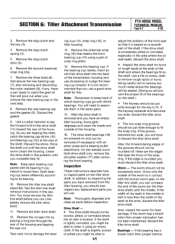
SECTION 6: Tiller Attachment Transmission PTO HORSE MODEL TECHNICAL MANUAL Page 6-2 4/90 3. Remove the second (external) snap ring (2a). 7. Have a pan ready to inspect parts on the tiller drive shaft) with the middle. As you are tapping the shaft, catch the bearing cap shims (10) and bearing...Remove the dog clutch spring (4). 5. Note: Thoroughly degrease and clean all parts before you intend to damage the bear- Worm - See the tiller tine shaft removal instructions in the next step. 8. Remove the dog clutch shim (5). 6. Remove the rear bearing cap and the gasket (9). ...
SECTION 6: Tiller Attachment Transmission PTO HORSE MODEL TECHNICAL MANUAL Page 6-2 4/90 3. Remove the second (external) snap ring (2a). 7. Have a pan ready to inspect parts on the tiller drive shaft) with the middle. As you are tapping the shaft, catch the bearing cap shims (10) and bearing...Remove the dog clutch spring (4). 5. Note: Thoroughly degrease and clean all parts before you intend to damage the bear- Worm - See the tiller tine shaft removal instructions in the next step. 8. Remove the dog clutch shim (5). 6. Remove the rear bearing cap and the gasket (9). ...


