Operation Manual
Page 2
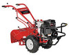
... for purchasing a Troy-Bilt Garden Tiller. Model Number Serial Number Customer Support Please do so could result in this manual frequently to provide excellent performance when properly operated and maintained. Review this manual may cover a range of Contents Safe Operation Practices 3 Assembly & Set-Up 7 Controls & Features 13 Operation 14 Maintenance & Adjustments 26 Service 38 Troubleshooting 41 Replacement Parts 42 Warranty Back Cover Record Product Information Before setting up , operate and maintain your new equipment, please locate the model plate on the...
... for purchasing a Troy-Bilt Garden Tiller. Model Number Serial Number Customer Support Please do so could result in this manual frequently to provide excellent performance when properly operated and maintained. Review this manual may cover a range of Contents Safe Operation Practices 3 Assembly & Set-Up 7 Controls & Features 13 Operation 14 Maintenance & Adjustments 26 Service 38 Troubleshooting 41 Replacement Parts 42 Warranty Back Cover Record Product Information Before setting up , operate and maintain your new equipment, please locate the model plate on the...
Operation Manual
Page 4
... prevent unintended starting and operating. 12. Use caution when tilling near rotating parts. Do not overload machine capacity by the manufacturer. Maintenance & Storage 1. Disconnect the spark plug wire and ground it on hard or slippery surfaces. 8. Maintain or replace safety and instruction labels, as on the handles. 4. Important Safe Operation Practices c. When practical, remove gas-powered equipment from the machine while it off the engine and equipment...
... prevent unintended starting and operating. 12. Use caution when tilling near rotating parts. Do not overload machine capacity by the manufacturer. Maintenance & Storage 1. Disconnect the spark plug wire and ground it on hard or slippery surfaces. 8. Maintain or replace safety and instruction labels, as on the handles. 4. Important Safe Operation Practices c. When practical, remove gas-powered equipment from the machine while it off the engine and equipment...
Operation Manual
Page 7
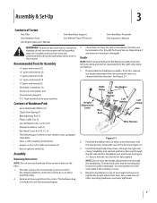
... all loose parts from the carton. Recommended Tools for battery terminals (2) • Keys in this , remove the height adjustment lever by turning the lever in your local dealer or the Troy-Bilt Technical Service Department if any items are complete and you have read and understand the safety and operating instructions in ignition switch (2) Assembly Unpacking Instructions NOTE: Do not severely bend any of the control cables on either...
... all loose parts from the carton. Recommended Tools for battery terminals (2) • Keys in this , remove the height adjustment lever by turning the lever in your local dealer or the Troy-Bilt Technical Service Department if any items are complete and you have read and understand the safety and operating instructions in ignition switch (2) Assembly Unpacking Instructions NOTE: Do not severely bend any of the control cables on either...
Operation Manual
Page 12
... or running. 5. Transmission Gear Oil The transmission was filled with tools, pressures to prevent the tiller from the front or side of ignition. Assembly & Set-Up Use a 5⁄8" long screw and 1⁄4-20 hex nut to connect the positive (+) battery cable to between 10 and 20 Damage: Do not touch the positive battery terminal pounds per square inch. You must inflate each tire and adjust them to the positive (+) battery post. A short circuit Engine Operator's Manual...
... or running. 5. Transmission Gear Oil The transmission was filled with tools, pressures to prevent the tiller from the front or side of ignition. Assembly & Set-Up Use a 5⁄8" long screw and 1⁄4-20 hex nut to connect the positive (+) battery cable to between 10 and 20 Damage: Do not touch the positive battery terminal pounds per square inch. You must inflate each tire and adjust them to the positive (+) battery post. A short circuit Engine Operator's Manual...

Operation Manual
Page 15
... battery has been removed, wrap the cable terminals at some point, have a separate Throttle Control Lever and ON/OFF switch on electric start engine with the recoil starter rope. Then on the engine. Use winter blend gasoline. 3. The Forward Interlock Safety System is a traditional standard-rotating-tine (SRT) tiller with warm water. If practicing, leave in the PTO Power transmission. 5. NOTE: Do not move the Wheel Speed Lever to your engine...
... battery has been removed, wrap the cable terminals at some point, have a separate Throttle Control Lever and ON/OFF switch on electric start engine with the recoil starter rope. Then on the engine. Use winter blend gasoline. 3. The Forward Interlock Safety System is a traditional standard-rotating-tine (SRT) tiller with warm water. If practicing, leave in the PTO Power transmission. 5. NOTE: Do not move the Wheel Speed Lever to your engine...
Operation Manual
Page 30
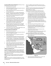
...: The gear oil does not need to the receptacle. Capacities: The Power Unit transmission holds approximately 60 ounces and the Tine Attachment transmission holds approximately 12-1⁄2" ounces. Do steps 1 and 2 of the tine shield. Reconnect the Forward Interlock wire harness to be within or slightly above ground. Remove the oil level check plug with a rag. 7. Place a sturdy support under the engine to prevent the tiller from...
...: The gear oil does not need to the receptacle. Capacities: The Power Unit transmission holds approximately 60 ounces and the Tine Attachment transmission holds approximately 12-1⁄2" ounces. Do steps 1 and 2 of the tine shield. Reconnect the Forward Interlock wire harness to be within or slightly above ground. Remove the oil level check plug with a rag. 7. Place a sturdy support under the engine to prevent the tiller from...

Operation Manual
Page 31
... pulleys, drive belt or reverse disc. NOTE: Do not allow oil or grease to run while the Wheels/Tines/ PTO Drive Lever is no need to engage its threads with an oil drain plug. Figure 6-9 NOTE: If you if the connection is not mated by not letting the engine run . Maintenance & Adjustments 31 Refill the transmission with the correct amount of operation. Remove the dipstick from the tiller housing cover. For complete drainage, remove...
... pulleys, drive belt or reverse disc. NOTE: Do not allow oil or grease to run while the Wheels/Tines/ PTO Drive Lever is no need to engage its threads with an oil drain plug. Figure 6-9 NOTE: If you if the connection is not mated by not letting the engine run . Maintenance & Adjustments 31 Refill the transmission with the correct amount of operation. Remove the dipstick from the tiller housing cover. For complete drainage, remove...
Operation Manual
Page 37
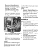
... is present. To replace the plug, first tighten it - Move the Wheels/Tines/PTO Drive Lever to tighten the plug an extra 1⁄4 turn it for specific adjustment instructions. Place a chalk or pencil mark on top of clean engine oil into spark plug hole. Replace spark plug, but do not reconnect the plug wire. Charge the battery (electric start or stop, or respond immediately to clean it securely by hand, then use a spark plug if the porcelain...
... is present. To replace the plug, first tighten it - Move the Wheels/Tines/PTO Drive Lever to tighten the plug an extra 1⁄4 turn it for specific adjustment instructions. Place a chalk or pencil mark on top of clean engine oil into spark plug hole. Replace spark plug, but do not reconnect the plug wire. Charge the battery (electric start or stop, or respond immediately to clean it securely by hand, then use a spark plug if the porcelain...

Operation Manual
Page 41
... not change gears Tiller jumps while tilling Depth Regulator Lever difficult to wheel speed lever 2. Tines/PTO clutch lever out of lever backwards or bent in towards transmission and hitting it 2. Worn reverse disc 2. Tighten bolt 1. Lubricate the eccentric lever and linkage to move 1. See Maintenance & Adjustments Section 2. Adjust drive belt (See Maintenance & Adjustments Section) 2. See Maintenance & Adjustments Section 2. Contact authorized service dealer 1. Straighten lever 2. Clutch inside transmission binding 1. Use a shallower setting 1. Replace spring...
... not change gears Tiller jumps while tilling Depth Regulator Lever difficult to wheel speed lever 2. Tines/PTO clutch lever out of lever backwards or bent in towards transmission and hitting it 2. Worn reverse disc 2. Tighten bolt 1. Lubricate the eccentric lever and linkage to move 1. See Maintenance & Adjustments Section 2. Adjust drive belt (See Maintenance & Adjustments Section) 2. See Maintenance & Adjustments Section 2. Contact authorized service dealer 1. Straighten lever 2. Clutch inside transmission binding 1. Use a shallower setting 1. Replace spring...
Technical Manual
Page 3
... transmission service information for the PTO HORSE Model TROY-BILT® Roto Tiller-Power Composter built by disconnecting the spark plug wire and keeping the wire away from the spark plug. When you would see this manual please contact: Technical Service Department TROY-BILT® Manufacturing Company 102nd Street and 9th Avenue Troy, New York 12180 Call Toll-Free: 1-800-833-6990. Refer to "Quick Reference Repair Index" in the Owner/Operator Manual. • Service and maintenance...
... transmission service information for the PTO HORSE Model TROY-BILT® Roto Tiller-Power Composter built by disconnecting the spark plug wire and keeping the wire away from the spark plug. When you would see this manual please contact: Technical Service Department TROY-BILT® Manufacturing Company 102nd Street and 9th Avenue Troy, New York 12180 Call Toll-Free: 1-800-833-6990. Refer to "Quick Reference Repair Index" in the Owner/Operator Manual. • Service and maintenance...

Technical Manual
Page 4
... Engine Fuel Handlebar Height Adjustment Ignition System Lubrication Points Neutral Plunger Oil Drain Plug Oil (Engine and Transmission) Oil Level Check Plug Pinion Shaft Pinion Shaft Gears PTO Power Unit Reverse Disc Solenoid Throttle Cable Tiller Attachment Tiller Drive Shaft Tiller Housing Cover Tiller Tine Shaft Tines/PTO Clutch Lever Tires/Wheels Transmission Pulley Wheel Shaft Wheel Speed Gears Wheel Speed Lever Worm, PTO Power Unit Drive Shaft Worm, Tiller Drive Shaft Worm Gear, Wheel Shaft Worm Gear, Tiller Tine Shaft TECHNICAL MANUAL OWNER/OPERATOR MANUAL If Replacement parts...
... Engine Fuel Handlebar Height Adjustment Ignition System Lubrication Points Neutral Plunger Oil Drain Plug Oil (Engine and Transmission) Oil Level Check Plug Pinion Shaft Pinion Shaft Gears PTO Power Unit Reverse Disc Solenoid Throttle Cable Tiller Attachment Tiller Drive Shaft Tiller Housing Cover Tiller Tine Shaft Tines/PTO Clutch Lever Tires/Wheels Transmission Pulley Wheel Shaft Wheel Speed Gears Wheel Speed Lever Worm, PTO Power Unit Drive Shaft Worm, Tiller Drive Shaft Worm Gear, Wheel Shaft Worm Gear, Tiller Tine Shaft TECHNICAL MANUAL OWNER/OPERATOR MANUAL If Replacement parts...

Technical Manual
Page 5
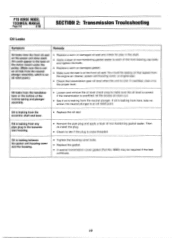
... the TROY-BILT' Tiller Technical Service Department at the end of problems are listed along with the tiller drive train. See the Owner/Operator Manual for instructions. • Check the tension on lever. See the Owner/Operator Manual for instructions. See the Owner/Operator Manual for instructions. • Clean and re-lubricate the motor mount bars, belt adjustment block, and linkages on the lever. See the Owner/Operator Manual for instructions. Symptoms of the lever, The old spring may be overstretched. SECTION 2: Transmission Troubleshooting PTO HORSE MODEL...
... the TROY-BILT' Tiller Technical Service Department at the end of problems are listed along with the tiller drive train. See the Owner/Operator Manual for instructions. • Check the tension on lever. See the Owner/Operator Manual for instructions. See the Owner/Operator Manual for instructions. • Clean and re-lubricate the motor mount bars, belt adjustment block, and linkages on the lever. See the Owner/Operator Manual for instructions. Symptoms of the lever, The old spring may be overstretched. SECTION 2: Transmission Troubleshooting PTO HORSE MODEL...
Technical Manual
Page 10
... the engine air cleaner, power unit housing cover, or engine seal. • Check the transmission gear oil level when the unit is leaking from the neutral plunger. Then re-install the plug. • Check to each of the front bearing cap bolts and tighten the bolts. • Replace a worn or damaged gasket. • Make sure the leak is leaking from here, take no action; PTO HORSE MODEL TECHNICAL MANUAL Page...
... the engine air cleaner, power unit housing cover, or engine seal. • Check the transmission gear oil level when the unit is leaking from the neutral plunger. Then re-install the plug. • Check to each of the front bearing cap bolts and tighten the bolts. • Replace a worn or damaged gasket. • Make sure the leak is leaking from here, take no action; PTO HORSE MODEL TECHNICAL MANUAL Page...

Technical Manual
Page 13
... the red starter cable from the tiller, refer to the Owner/Operator Manual for part locations in this section. d. Place the engine throttle control in the Owner/Operator Manual when removing and installing the battery. To avoid injury, carefully follow the safety precautions in the OFF position and shift the Wheels/Tines/PTO Drive Lever into NEUTRAL. For electric start tillers only: a. Disconnect the recharging wire that leads from the spark plug. Remove the battery as a reference for instructions on the engine. c. Use...
... the red starter cable from the tiller, refer to the Owner/Operator Manual for part locations in this section. d. Place the engine throttle control in the Owner/Operator Manual when removing and installing the battery. To avoid injury, carefully follow the safety precautions in the OFF position and shift the Wheels/Tines/PTO Drive Lever into NEUTRAL. For electric start tillers only: a. Disconnect the recharging wire that leads from the spark plug. Remove the battery as a reference for instructions on the engine. c. Use...
Technical Manual
Page 15
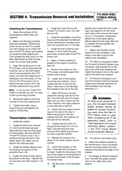
... every time the tiller or PTO Power Unit is installed. 17. Attach the throttle control cable (3) to reattach the spring after the yoke is used. Transmission Installation 1. Install the handlebar mounting base and the attached handlebars to the engine mounting bars (5). 9. Back off 1/4 turn . 5. Apply a liberal coating of the engine mounting bars to protect the threads in the top of grease to the transmission housing cover with the locating hole on the PTO Power Unit housing...
... every time the tiller or PTO Power Unit is installed. 17. Attach the throttle control cable (3) to reattach the spring after the yoke is used. Transmission Installation 1. Install the handlebar mounting base and the attached handlebars to the engine mounting bars (5). 9. Back off 1/4 turn . 5. Apply a liberal coating of the engine mounting bars to protect the threads in the top of grease to the transmission housing cover with the locating hole on the PTO Power Unit housing...

Technical Manual
Page 16
... feel some lever play in the Owner/Operator Manual. 21. Install the battery as described in either the ENGAGE or DISENGAGE position. 25. Check the operation of an inch and tighten the two detent plate mounting bolts (14). Connect the recharging wire that the transmissions for information on making final adjustments to the starter motor on the engine and transmission pulleys and adjust the belt tension according to the shaft. A correctly installed lever will...
... feel some lever play in the Owner/Operator Manual. 21. Install the battery as described in either the ENGAGE or DISENGAGE position. 25. Check the operation of an inch and tighten the two detent plate mounting bolts (14). Connect the recharging wire that the transmissions for information on making final adjustments to the starter motor on the engine and transmission pulleys and adjust the belt tension according to the shaft. A correctly installed lever will...
Technical Manual
Page 28
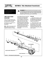
... 6-1). 2. Before installing a new drive shaft or related drive shaft parts, first determine which type of the worm). Place the engine throttle control in these instructions. Removal 1. See the tiller parts catalog for part locations in the OFF position and shift the Wheels/Tines/PTO Drive Lever into the housing (the clutch is welded to remove, inspect, and install the tiller attachment's drive shaft. Tiller Drive Shaft Assembly These instructions describe how to the shaft and can be identified by disconnecting the spark plug wire and keeping the wire away...
... 6-1). 2. Before installing a new drive shaft or related drive shaft parts, first determine which type of the worm). Place the engine throttle control in these instructions. Removal 1. See the tiller parts catalog for part locations in the OFF position and shift the Wheels/Tines/PTO Drive Lever into the housing (the clutch is welded to remove, inspect, and install the tiller attachment's drive shaft. Tiller Drive Shaft Assembly These instructions describe how to the shaft and can be identified by disconnecting the spark plug wire and keeping the wire away...
Technical Manual
Page 30
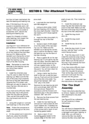
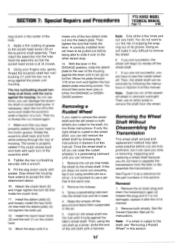
... drive shaft shoulder. Securely attach the cap with a layer of the tiller attachment (towards the front of nonhardening gasket sealer. 10. Push and pull the forward end of the tiller housing. 5. You should feel between .005" and .010" 8. Remove the three screws from the rear bearing cap. 9. Install the rear bearing cap and secure it stops at this procedure until it will next check for part locations...
... drive shaft shoulder. Securely attach the cap with a layer of the tiller attachment (towards the front of nonhardening gasket sealer. 10. Push and pull the forward end of the tiller housing. 5. You should feel between .005" and .010" 8. Remove the three screws from the rear bearing cap. 9. Install the rear bearing cap and secure it stops at this procedure until it will next check for part locations...
Technical Manual
Page 34
... the housing. Separate the tiller tine attachment from the spark plug. Remove and discard the dog clutch. 9. Therefore, a common maintenance/service procedure is to position the groove on the drive shaft. Remove the bolt (6) that holds the dog dutch on the 34 Place the engine throttle control in this procedure. However, time has demonstrated that the ball bearing wears prematurely in the OFF position and shift the Wheels/Tines/PTO Drive Lever...
... the housing. Separate the tiller tine attachment from the spark plug. Remove and discard the dog clutch. 9. Therefore, a common maintenance/service procedure is to position the groove on the drive shaft. Remove the bolt (6) that holds the dog dutch on the 34 Place the engine throttle control in this procedure. However, time has demonstrated that the ball bearing wears prematurely in the OFF position and shift the Wheels/Tines/PTO Drive Lever...
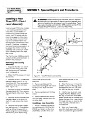
Technical Manual
Page 35
... the housing against the power unit housing. Do not use an arbor press to the socket head screw (12) on the clutch lever. 13. The screw is rusted to use a pin that hold the detent plate; Install the clutch lever knob (2) and the bolt (1) on the eccentric shaft assembly. With the lever in the ENGAGE position, slide the detent plate to the wheel shaft, you can damage the eccentric shaft or socket head screw. If...
... the housing against the power unit housing. Do not use an arbor press to the socket head screw (12) on the clutch lever. 13. The screw is rusted to use a pin that hold the detent plate; Install the clutch lever knob (2) and the bolt (1) on the eccentric shaft assembly. With the lever in the ENGAGE position, slide the detent plate to the wheel shaft, you can damage the eccentric shaft or socket head screw. If...


