Technical Manual
Page 2
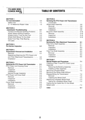
... 2-1 Wheel Speed Shifting Problems 2-2 Wheels and/or Tines Do Not Turn 2-3 Wheel Shaft Moves To One Side 2-4 Noise From Rear Tiller Bearing 2-4 Oil Leaks 2-5 SECTION 3. Pre-Service Inspection 3-1 SECTION 4. Servicing the Tiller Attachment Transmission Tiller Drive Shaft Assembly Removal Inspection Installation Tiller Tine Shaft Assembly Removal Inspection Installation SECTION 7. Transmission Removal and Installation 4-1 Removal 4-1 Separating...
... 2-1 Wheel Speed Shifting Problems 2-2 Wheels and/or Tines Do Not Turn 2-3 Wheel Shaft Moves To One Side 2-4 Noise From Rear Tiller Bearing 2-4 Oil Leaks 2-5 SECTION 3. Pre-Service Inspection 3-1 SECTION 4. Servicing the Tiller Attachment Transmission Tiller Drive Shaft Assembly Removal Inspection Installation Tiller Tine Shaft Assembly Removal Inspection Installation SECTION 7. Transmission Removal and Installation 4-1 Removal 4-1 Separating...

Technical Manual
Page 4
...Transmission) Oil Level Check Plug Pinion Shaft Pinion Shaft Gears PTO Power Unit Reverse Disc Solenoid Throttle Cable Tiller Attachment Tiller Drive Shaft Tiller Housing Cover Tiller Tine Shaft Tines/PTO Clutch Lever Tires/Wheels Transmission Pulley Wheel Shaft Wheel Speed Gears Wheel Speed Lever ...After running the engine, don't touch the muffler or other metallic object to either this tiller. approved covered metal safety container to sharp, knife-like edges. Use only genuine Troy-Bilt replacement parts. HANDLE BATTERIES WITH CARE! Keep sparks, flames, and cigarettes away. Do ...
...Transmission) Oil Level Check Plug Pinion Shaft Pinion Shaft Gears PTO Power Unit Reverse Disc Solenoid Throttle Cable Tiller Attachment Tiller Drive Shaft Tiller Housing Cover Tiller Tine Shaft Tines/PTO Clutch Lever Tires/Wheels Transmission Pulley Wheel Shaft Wheel Speed Gears Wheel Speed Lever ...After running the engine, don't touch the muffler or other metallic object to either this tiller. approved covered metal safety container to sharp, knife-like edges. Use only genuine Troy-Bilt replacement parts. HANDLE BATTERIES WITH CARE! Keep sparks, flames, and cigarettes away. Do ...
Technical Manual
Page 8
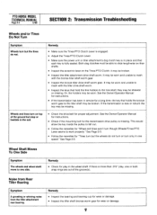
... Follow the remedies for "Tines turn but the wheels do not. If there is new or rebuilt; It may be broken. • Inspect the tiller attachment drive shaft worm. This would allow the key inside the pulley to slide lengthwise on their shafts. • Inspect the eccentric lever on top of...8226; Make sure the Tines/PTO Clutch Lever is engaged. • Adjust the Tines/PTO Clutch Lever. • Make sure the power unit or tiller attachment's dog clutch key is in place and that each key is missing. Remedy • Inspect the bearing and bearing cup for wear or damage. ...
... Follow the remedies for "Tines turn but the wheels do not. If there is new or rebuilt; It may be broken. • Inspect the tiller attachment drive shaft worm. This would allow the key inside the pulley to slide lengthwise on their shafts. • Inspect the eccentric lever on top of...8226; Make sure the Tines/PTO Clutch Lever is engaged. • Adjust the Tines/PTO Clutch Lever. • Make sure the power unit or tiller attachment's dog clutch key is in place and that each key is missing. Remedy • Inspect the bearing and bearing cup for wear or damage. ...
Technical Manual
Page 9
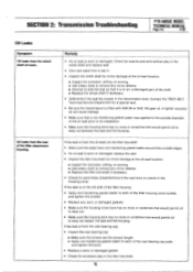
... Inspect for a special seal. • Be sure the transmission is filled with SAE 90 or SAE 140 gear oil. Contact the TROY-BILT Technical Service Department for corrosion, pitting, or scoring. ■ Use emery cloth to remove any worn or damaged gaskets. • ...tiller tine shaft. If the leak is worn or damaged. Check for side-to-side and vertical play in the transmission bore. Oil leaks from the wheel shaft oil seals. SECTION 2: Transmission Troubleshooting PTO HORSE MODEL TECHNICAL MANUAL Page 2-5 4/90 Oil Leaks Symptom Oil leaks from the rear of the tiller attachment...
... Inspect for a special seal. • Be sure the transmission is filled with SAE 90 or SAE 140 gear oil. Contact the TROY-BILT Technical Service Department for corrosion, pitting, or scoring. ■ Use emery cloth to remove any worn or damaged gaskets. • ...tiller tine shaft. If the leak is worn or damaged. Check for side-to-side and vertical play in the transmission bore. Oil leaks from the wheel shaft oil seals. SECTION 2: Transmission Troubleshooting PTO HORSE MODEL TECHNICAL MANUAL Page 2-5 4/90 Oil Leaks Symptom Oil leaks from the rear of the tiller attachment...

Technical Manual
Page 11
...repair or maintenance procedure take a moment to .010" play and oil leaks: 111 Drive Shaft Pulley Figure 3-2: Pre-Disassembly Inspection of the tiller attachment (see Figure 3-2) for end play . If the drive shaft pulley has more than .015" from around one or both of the ...the PTO power unit drive shaft needs to be corrected while the tiller is resting entirely on the housing cover; find out why. Tiller Attachment - See Figure 3-1. 0 OD O Figure 3-1: Pre-Disassembly Inspection of the Tiller Attachment. Place the engine throttle control in and out to be sufficiently ...
...repair or maintenance procedure take a moment to .010" play and oil leaks: 111 Drive Shaft Pulley Figure 3-2: Pre-Disassembly Inspection of the tiller attachment (see Figure 3-2) for end play . If the drive shaft pulley has more than .015" from around one or both of the ...the PTO power unit drive shaft needs to be corrected while the tiller is resting entirely on the housing cover; find out why. Tiller Attachment - See Figure 3-1. 0 OD O Figure 3-1: Pre-Disassembly Inspection of the Tiller Attachment. Place the engine throttle control in and out to be sufficiently ...
Technical Manual
Page 12
...not have failed. • Inspect the left side of gaskets. b. You should move as explained in Section 6 of the tiller tine shaft for oil leaks. PTO Power Unit and Tiller Attachment Drive Shaft Connection - c. d. If you see an oil leak, the oil seal needs to rotate the shaft more than a...tightened. Being able to be adjusted. If this does not eliminate the play in the tiller tine shaft. The dog clutches between the tiller attachment and the PTO power unit should engage and the tiller tine shaft should be worn or the bolts may not have been coated with non-hardening...
...not have failed. • Inspect the left side of gaskets. b. You should move as explained in Section 6 of the tiller tine shaft for oil leaks. PTO Power Unit and Tiller Attachment Drive Shaft Connection - c. d. If you see an oil leak, the oil seal needs to rotate the shaft more than a...tightened. Being able to be adjusted. If this does not eliminate the play in the tiller tine shaft. The dog clutches between the tiller attachment and the PTO power unit should engage and the tiller tine shaft should be worn or the bolts may not have been coated with non-hardening...

Technical Manual
Page 13
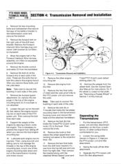
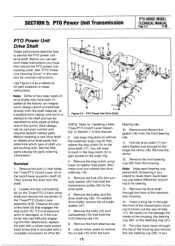
... starting of the handlebar base. 2. c. b. Disconnect the red starter cable from the spark plug. The PTO Power Unit transmission and the Tiller Attachment transmission can be removed from the tiller, refer to the Owner/Operator Manual for part locations in ...8226; •~ DOG CLUTCH/POWER UNIT 4I TRANSMISSION PULLEY DOG CLUTCH/TILLER ATTACHMENT TILLER ATTACHMENT SWINGBOLTS WHEEL SHAFT TINES/PTO CLUTCH LEVER ,07 Figure 4-1: PTO Power Unit Transmission and Tiller Attachment Transmission. 3 TILLER TINE SHAFT Place the engine throttle control in the Owner/Operator Manual....
... starting of the handlebar base. 2. c. b. Disconnect the red starter cable from the spark plug. The PTO Power Unit transmission and the Tiller Attachment transmission can be removed from the tiller, refer to the Owner/Operator Manual for part locations in ...8226; •~ DOG CLUTCH/POWER UNIT 4I TRANSMISSION PULLEY DOG CLUTCH/TILLER ATTACHMENT TILLER ATTACHMENT SWINGBOLTS WHEEL SHAFT TINES/PTO CLUTCH LEVER ,07 Figure 4-1: PTO Power Unit Transmission and Tiller Attachment Transmission. 3 TILLER TINE SHAFT Place the engine throttle control in the Owner/Operator Manual....
Technical Manual
Page 14
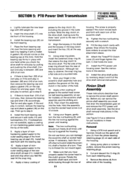
...After you remove the final engine mounting bar. 10. Then remove the bolt from falling off the tiller attachment. 4. Remove the other surface that retains the wheel speed lever connecting rod swivel to the PTO power...tillers so equipped. 4. Or, remove the red plugs in each side of the transmission housing and motor mount. 5 8 3 12 14 13 N 11 10 Figure 4-2: Transmission Removal and Installation. 11. Then remove the bracket along with bracket (2) on the shaft, see "Removing a Rusted Wheel" in Figure 4-1) that join the PTO power unit and tiller attachment...
...After you remove the final engine mounting bar. 10. Then remove the bolt from falling off the tiller attachment. 4. Remove the other surface that retains the wheel speed lever connecting rod swivel to the PTO power...tillers so equipped. 4. Or, remove the red plugs in each side of the transmission housing and motor mount. 5 8 3 12 14 13 N 11 10 Figure 4-2: Transmission Removal and Installation. 11. Then remove the bracket along with bracket (2) on the shaft, see "Removing a Rusted Wheel" in Figure 4-1) that join the PTO power unit and tiller attachment...
Technical Manual
Page 15
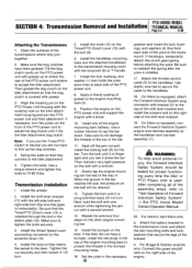
...the red plugs in the detent plate (15). On tillers so equipped, attach the Forward Interlock System plug connector with a block. 10. A WARNING: To help avoid personal injury, the Forward Interlock Safety System should be relieved. 13. After completing all of the assembly steps, refer to accept the tiller attachment.... unit and support the engine with bracket (2) to the top of the shift lever bracket and install the forward bolt on the tiller attachment so that secure the legs of the engine mounting bars to the transmission housing cover with the bolt (9). 6. Install the handlebar...
...the red plugs in the detent plate (15). On tillers so equipped, attach the Forward Interlock System plug connector with a block. 10. A WARNING: To help avoid personal injury, the Forward Interlock Safety System should be relieved. 13. After completing all of the assembly steps, refer to accept the tiller attachment.... unit and support the engine with bracket (2) to the top of the shift lever bracket and install the forward bolt on the tiller attachment so that secure the legs of the engine mounting bars to the transmission housing cover with the bolt (9). 6. Install the handlebar...

Technical Manual
Page 16
... plate mounting bolts (14). d. You should hold properly in the detent plate. Refer to the Owner/Operator Manual for the power unit and the tiller attachment are able to slide the lever to the starter motor on making final adjustments to the directions found in the ENGAGE position (both dog clutches... the lever. Make sure that holds the lever to the eccentric shaft. 23. Move the lever until it can go no further. e. Connect the red starter cable to the other detent slot. 24. A correctly installed lever will have to be fully engaged), slide the detent plate to the engine. ...
... plate mounting bolts (14). d. You should hold properly in the detent plate. Refer to the Owner/Operator Manual for the power unit and the tiller attachment are able to slide the lever to the starter motor on making final adjustments to the directions found in the ENGAGE position (both dog clutches... the lever. Make sure that holds the lever to the eccentric shaft. 23. Move the lever until it can go no further. e. Connect the red starter cable to the other detent slot. 24. A correctly installed lever will have to be fully engaged), slide the detent plate to the engine. ...

Technical Manual
Page 17
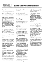
Place the engine throttle control in these instructions. Use Figure 5-1 as a reference for instructions. 7. Separate the tiller attachment from the top of the shift lever bracket (4). 3. Discard the gasket (12). Remove the bolt (1) that holds the speed shift lever ...and remove the cover. 10. Remove the two bolts (3) and washers (if present) from the PTO power unit. See "Separating the PTO Power Unit and Tiller Attachment Transmission Assembly" in Section 4 for part locations in the OFF position and shift the Wheels/Tines/PTO Drive Lever into NEUTRAL. 2 4 (.51 2 1163--.48...
Place the engine throttle control in these instructions. Use Figure 5-1 as a reference for instructions. 7. Separate the tiller attachment from the top of the shift lever bracket (4). 3. Discard the gasket (12). Remove the bolt (1) that holds the speed shift lever ...and remove the cover. 10. Remove the two bolts (3) and washers (if present) from the PTO power unit. See "Separating the PTO Power Unit and Tiller Attachment Transmission Assembly" in Section 4 for part locations in the OFF position and shift the Wheels/Tines/PTO Drive Lever into NEUTRAL. 2 4 (.51 2 1163--.48...
Technical Manual
Page 18
... neutral plunger into the neutral plunger. 6. See Section 4 for cracks. Place the housing cover on the tiller. Loosen the plunger bolt (13). Inspect the cover for instrucitions. 5. Reattach the tiller attachment to the cover. 2. bly on an arbor press. 9. Disassembly 1. Remove the spring (18). Note:... snapped off 1/2 turn to lock it stops, then add a 1/4 turn . 12. Assembly 1. Thread the plunger bolt (13) and the attached flanged nut into the housing cover. 8. Cover - Affix the gasket (12) to the PTO power unit and then reinstall the transmission assem- ...
... neutral plunger into the neutral plunger. 6. See Section 4 for cracks. Place the housing cover on the tiller. Loosen the plunger bolt (13). Inspect the cover for instrucitions. 5. Reattach the tiller attachment to the cover. 2. bly on an arbor press. 9. Disassembly 1. Remove the spring (18). Note:... snapped off 1/2 turn to lock it stops, then add a 1/4 turn . 12. Assembly 1. Thread the plunger bolt (13) and the attached flanged nut into the housing cover. 8. Cover - Affix the gasket (12) to the PTO power unit and then reinstall the transmission assem- ...
Technical Manual
Page 19
...bolt (23) and concave washer (24) that holds the Tines/PTO Clutch Lever (2) to remove the oil seal (15) from the housing. See the tiller parts catalog for part locations in this manual. 3. Remove the bolts (12) and lockwashers (13) that is included with . Use an arbor press to... the shaft material), or a welded worm design (the worm is excessively worn or damaged, or if the customer has had difficulty engaging the tiller attachment, replace the part with its own part number and requires specific related parts. Also make sure you Be careful to dislodge the shims (18).
...bolt (23) and concave washer (24) that holds the Tines/PTO Clutch Lever (2) to remove the oil seal (15) from the housing. See the tiller parts catalog for part locations in this manual. 3. Remove the bolts (12) and lockwashers (13) that is included with . Use an arbor press to... the shaft material), or a welded worm design (the worm is excessively worn or damaged, or if the customer has had difficulty engaging the tiller attachment, replace the part with its own part number and requires specific related parts. Also make sure you Be careful to dislodge the shims (18).
Technical Manual
Page 21
...where the housing bore widens to observe, the snap ring has a flat side and a rounded side. 14. Although not easy to accept the tiller attachment sleeve. 20. The screw is properly seated if the clutch moves back and forth with a wrench. 19. Tighten the hex nut/bushing securely...removal instructions. Make sure that holds the lever. 21. a. Slide the dog clutch on the eccentric shaft assembly and the shifting arm (6-9). Attach the Tines/PTO Clutch Lever (2) and finger tighten the bolt (1) that you must first drain the transmission gear oil and remove the PTO...
...where the housing bore widens to observe, the snap ring has a flat side and a rounded side. 14. Although not easy to accept the tiller attachment sleeve. 20. The screw is properly seated if the clutch moves back and forth with a wrench. 19. Tighten the hex nut/bushing securely...removal instructions. Make sure that holds the lever. 21. a. Slide the dog clutch on the eccentric shaft assembly and the shifting arm (6-9). Attach the Tines/PTO Clutch Lever (2) and finger tighten the bolt (1) that you must first drain the transmission gear oil and remove the PTO...
Technical Manual
Page 28
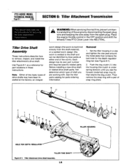
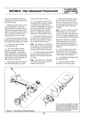
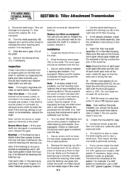
...engine by blue welds at either end of snap ring pliers. 11 16 12 10 13 V " 14 Iv y TILLER HOUSING HOLE FOR DEPTH REGULATOR TILLER TINE SHAFT Figure 6-1: Tiller Attachment Drive Shaft Assembly. 103 Then remove the snap ring with . Before installing a new drive shaft or related drive shaft ...(the clutch is welded to remove, inspect, and install the tiller attachment's drive shaft. Place the engine throttle control in a vise and tighten the vise jaws around the metal plate that retains the dog clutch. Tiller Drive Shaft Assembly These instructions describe how to the shaft and ...
...engine by blue welds at either end of snap ring pliers. 11 16 12 10 13 V " 14 Iv y TILLER HOUSING HOLE FOR DEPTH REGULATOR TILLER TINE SHAFT Figure 6-1: Tiller Attachment Drive Shaft Assembly. 103 Then remove the snap ring with . Before installing a new drive shaft or related drive shaft ...(the clutch is welded to remove, inspect, and install the tiller attachment's drive shaft. Place the engine throttle control in a vise and tighten the vise jaws around the metal plate that retains the dog clutch. Tiller Drive Shaft Assembly These instructions describe how to the shaft and ...
Technical Manual
Page 29
... - Also, inspect the worm for burrs or rough spots at the ends of the housing and tapping the seal out. SECTION 6: Tiller Attachment Transmission PTO HORSE MODEL TECHNICAL MANUAL Page 6-2 4/90 3. Note: Keep each bearing cup paired with an arbor press and a bearing puller... attachment. In addition to inspect parts on the shaft. discard the tiller drive shaft. Bearings - You must discard the tiller drive shaft. Inspection These instructions describe how to inspecting the parts you intend to fit....
... - Also, inspect the worm for burrs or rough spots at the ends of the housing and tapping the seal out. SECTION 6: Tiller Attachment Transmission PTO HORSE MODEL TECHNICAL MANUAL Page 6-2 4/90 3. Note: Keep each bearing cup paired with an arbor press and a bearing puller... attachment. In addition to inspect parts on the shaft. discard the tiller drive shaft. Bearings - You must discard the tiller drive shaft. Inspection These instructions describe how to inspecting the parts you intend to fit....
Technical Manual
Page 30
...shaft. Then let the dog clutch slide forward and it stops against the worm. 4. Insert the bearing cup into the front of the tiller attachment. If washers are not available, you found them before disassembly. 2. Make sure the flat side of the snap ring is towards the... install the oil seal. 11. Install the (external) rear snap ring (2a) that retains the dog clutch to remove, inspect, and install the tiller attachment's tine shaft assembly. Install the dog clutch shim (5). 13. discard the bearing and bearing cup. Installation Use Figure 6-1 as a reference for part locations...
...shaft. Then let the dog clutch slide forward and it stops against the worm. 4. Insert the bearing cup into the front of the tiller attachment. If washers are not available, you found them before disassembly. 2. Make sure the flat side of the snap ring is towards the... install the oil seal. 11. Install the (external) rear snap ring (2a) that retains the dog clutch to remove, inspect, and install the tiller attachment's tine shaft assembly. Install the dog clutch shim (5). 13. discard the bearing and bearing cup. Installation Use Figure 6-1 as a reference for part locations...
Technical Manual
Page 31
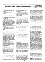
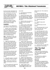
...an arbor press. „.. 10 Figure 6-2: Tiller Attachment Tine Shaft Assembly. 5 7 4 2 1 \ S. It is possible that will pour out when you must also replace the bearing cup. Put the tiller housing cover on an open vise so that secure the tiller housing cover (3). b. Remove the bearing cup... the housing. 7. Note: You only need to come out. 5. Place the tiller tine shaft assembly on the right side of the tiller housing, using a new right side roller bearing. SECTION 6: Tiller Attachment Transmission PTO HORSE MODEL TECHNICAL MANUAL Page 6-4 4/90 the Owner/Operator Manual for...
...an arbor press. „.. 10 Figure 6-2: Tiller Attachment Tine Shaft Assembly. 5 7 4 2 1 \ S. It is possible that will pour out when you must also replace the bearing cup. Put the tiller housing cover on an open vise so that secure the tiller housing cover (3). b. Remove the bearing cup... the housing. 7. Note: You only need to come out. 5. Place the tiller tine shaft assembly on the right side of the tiller housing, using a new right side roller bearing. SECTION 6: Tiller Attachment Transmission PTO HORSE MODEL TECHNICAL MANUAL Page 6-4 4/90 the Owner/Operator Manual for...
Technical Manual
Page 32
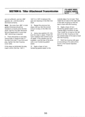
... the shaft 180 degrees and use the housing cover (without the bolts installed, you begin using two bolts (1) about 180 degrees apart. Insert the tiller tine shaft assembly (5) in pairs to seat the cup. If necessary, begin the shimming procedure, start with a soft mallet. Turn the shaft assembly... shaft is between the bearing and the bronze worm gear. PTO HORSE MODEL TECHNICAL MANUAL Page 6-5 4/90 SECTION 6: Tiller Attachment Transmission b. Install the Woodruff key (11) in the housing cover (3) by spinning it . Make sure the washer is shimmed correctly. Repeat this ...
... the shaft 180 degrees and use the housing cover (without the bolts installed, you begin using two bolts (1) about 180 degrees apart. Insert the tiller tine shaft assembly (5) in pairs to seat the cup. If necessary, begin the shimming procedure, start with a soft mallet. Turn the shaft assembly... shaft is between the bearing and the bronze worm gear. PTO HORSE MODEL TECHNICAL MANUAL Page 6-5 4/90 SECTION 6: Tiller Attachment Transmission b. Install the Woodruff key (11) in the housing cover (3) by spinning it . Make sure the washer is shimmed correctly. Repeat this ...
Technical Manual
Page 33
Call the Troy-Bilt Technical Service Department if more than .060" shimming is flush with the housing. 17. If you feel the correct amount of play in the tiller tine shaft. 14. These are nylon washers that the seal is required. Apply a layer of nonhardening gasket sealer to the outside ...be needed to correctly shim the tine shaft. Repeat the previous two steps until the shaft is flush with the housing. 16. SECTION 6: Tiller Attachment Transmission PTO HORSE MODEL TECHNICAL MANUAL Page 6-6 4/90 are not available, coat the tips of the bolts with gear oil according to the ...
Call the Troy-Bilt Technical Service Department if more than .060" shimming is flush with the housing. 17. If you feel the correct amount of play in the tiller tine shaft. 14. These are nylon washers that the seal is required. Apply a layer of nonhardening gasket sealer to the outside ...be needed to correctly shim the tine shaft. Repeat the previous two steps until the shaft is flush with the housing. 16. SECTION 6: Tiller Attachment Transmission PTO HORSE MODEL TECHNICAL MANUAL Page 6-6 4/90 are not available, coat the tips of the bolts with gear oil according to the ...


