Replacement Instructions
Page 1
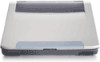
... make make ors -STOPPED- rn ine PC Card Manager. bay TOSHIBA Tough Enough for Today's World the right and lift it out HOD REMOVAL Pe cars 1 Pullout the ejed button of the PC card to disconnect the 1100 assembly d then= assembly out of the arrow 3 Slide the battery pack. FIELD REPLACEABLE UNIT DOCUMENTATION Satellite Prom" 4600 Series BATTERY PACK REMOVAL OPTIONAL PCMCIA CARO REMOVAL Battery pack release lever 1 Turn...
... make make ors -STOPPED- rn ine PC Card Manager. bay TOSHIBA Tough Enough for Today's World the right and lift it out HOD REMOVAL Pe cars 1 Pullout the ejed button of the PC card to disconnect the 1100 assembly d then= assembly out of the arrow 3 Slide the battery pack. FIELD REPLACEABLE UNIT DOCUMENTATION Satellite Prom" 4600 Series BATTERY PACK REMOVAL OPTIONAL PCMCIA CARO REMOVAL Battery pack release lever 1 Turn...
Replacement Instructions
Page 2
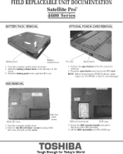
bracket Flat head screws 5 RODemove four M.el Ike head screws securing the H bracket . black screws a. nl:Crn= rodn' anlet:ge TOSHIBA Tough Enough tor Today's World the dTive MINI PCI CARD REMOVAL 5.4 a:' rts °" Memory clips 1 Tum the computer upside dovvn. 2 Remove two MES. remove 7tI0177,177'I"4de774°u "°4,Vr2"2":te PCI al black PCI slot cover securing the Mini Pct angle. H. FIELD REPLACEABLE UNIT DOCUMENTATION Satellite PrO' 4600 Series HOD REMOVAL MEMORY MODULE REMOVAL 1.5x1blac SCreWS 0.- -
bracket Flat head screws 5 RODemove four M.el Ike head screws securing the H bracket . black screws a. nl:Crn= rodn' anlet:ge TOSHIBA Tough Enough tor Today's World the dTive MINI PCI CARD REMOVAL 5.4 a:' rts °" Memory clips 1 Tum the computer upside dovvn. 2 Remove two MES. remove 7tI0177,177'I"4de774°u "°4,Vr2"2":te PCI al black PCI slot cover securing the Mini Pct angle. H. FIELD REPLACEABLE UNIT DOCUMENTATION Satellite PrO' 4600 Series HOD REMOVAL MEMORY MODULE REMOVAL 1.5x1blac SCreWS 0.- -
Replacement Instructions
Page 3
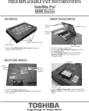
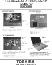
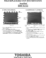
... securing Me len sole of the rp:gforlard M25'. black screws securing the keyboard TOSHIBA Tough Enough for Today's World FIELD REPLACEABLE UNIT DOCUMENTATION Satellite Prom" 4600 Series MODEM REMOVAL M2 br RJ11 Jack Modem slot cover lut25.4 black .1. the Keyboard holder at the top of ihe modem Lad cover KEYBOARD REMOVAL odem 3. I -11jack from the modem board Keyboard holder en the display panel 2. black screw 3 Remove two Pd25wl. Remove awegVlmglsthape se uri g d.
... securing Me len sole of the rp:gforlard M25'. black screws securing the keyboard TOSHIBA Tough Enough for Today's World FIELD REPLACEABLE UNIT DOCUMENTATION Satellite Prom" 4600 Series MODEM REMOVAL M2 br RJ11 Jack Modem slot cover lut25.4 black .1. the Keyboard holder at the top of ihe modem Lad cover KEYBOARD REMOVAL odem 3. I -11jack from the modem board Keyboard holder en the display panel 2. black screw 3 Remove two Pd25wl. Remove awegVlmglsthape se uri g d.
Replacement Instructions
Page 4
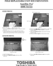
... top cover TOSHIBA Tough Enough for Today's World LED/Sensor stablefrom Ift267 LCD/FL P252 - Mac...Mite coaxialcable from P210 a. FIELD REPLACEABLE UNIT DOCUMENTATION Satellite Prom" 4600 Series KEYBOARD REMOVAL TOP COVER REMOVAL M2 Steblac Keyboard g: gl=rc=0V,%17=T system board and lift out me keyboard TOP COVER REMOVAL K, :,,ylbeoard M2 5,16 sb = Est' M2 5,6 black 1 Turn Me computer upside down and remove the VIL n.echlrrl2t7rwa - 6 lid2.5s6 black screws...
... top cover TOSHIBA Tough Enough for Today's World LED/Sensor stablefrom Ift267 LCD/FL P252 - Mac...Mite coaxialcable from P210 a. FIELD REPLACEABLE UNIT DOCUMENTATION Satellite Prom" 4600 Series KEYBOARD REMOVAL TOP COVER REMOVAL M2 Steblac Keyboard g: gl=rc=0V,%17=T system board and lift out me keyboard TOP COVER REMOVAL K, :,,ylbeoard M2 5,16 sb = Est' M2 5,6 black 1 Turn Me computer upside down and remove the VIL n.echlrrl2t7rwa - 6 lid2.5s6 black screws...
Replacement Instructions
Page 5
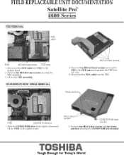
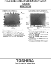
a ssy Iyisd.rn= MO cable from R.I63 on the system board :vas7e7s:c C0EIVI,R0M drive bracket bras et,7e'vCIV0aT0ZIre TOSHIBA Tough Enough for Today's World IMr6=1:2.5a6 brass screws securing the 3 Li out. CO-ROMIOVO ROM DRIVE REMOVAL M2.50 black screw. ° 5 IPsccoanneect the F00 cable from PJ58 on the 2. disconnect it from the FM, Brass washers PJ58 OM drive Slide me C0MV0-Ram driveB./INthDe-rRight. FIELD REPLACEABLE UNIT DOCUMENTATION Satellite Prom" 4600 Series FDD REMOVAL PJ63 M2.5. braes screw F. FDD assembly.
a ssy Iyisd.rn= MO cable from R.I63 on the system board :vas7e7s:c C0EIVI,R0M drive bracket bras et,7e'vCIV0aT0ZIre TOSHIBA Tough Enough for Today's World IMr6=1:2.5a6 brass screws securing the 3 Li out. CO-ROMIOVO ROM DRIVE REMOVAL M2.50 black screw. ° 5 IPsccoanneect the F00 cable from PJ58 on the 2. disconnect it from the FM, Brass washers PJ58 OM drive Slide me C0MV0-Ram driveB./INthDe-rRight. FIELD REPLACEABLE UNIT DOCUMENTATION Satellite Prom" 4600 Series FDD REMOVAL PJ63 M2.5. braes screw F. FDD assembly.
Replacement Instructions
Page 6
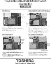
... rdbettery out of the sound/FIR board to Msconneriv from the board SOUNDIFIR BOARD REMOVAL GI Prn br M256 flat head screws 1. Remora iM1e 3. wirele:I=VO board a. r Pee rrgb glZfrO'rTRje7r0Panled' R„03 and lilt out both speakers SoundrIR board 1 Remove one Arl2.5. me back side of the slot SPEAKERS REMOVAL Wireless .M.0 board Wireless switch/LED board cable 1. remove careless switch/LED board cable from P.1701 on the system board TOSHIBA Tough Enough for...
... rdbettery out of the sound/FIR board to Msconneriv from the board SOUNDIFIR BOARD REMOVAL GI Prn br M256 flat head screws 1. Remora iM1e 3. wirele:I=VO board a. r Pee rrgb glZfrO'rTRje7r0Panled' R„03 and lilt out both speakers SoundrIR board 1 Remove one Arl2.5. me back side of the slot SPEAKERS REMOVAL Wireless .M.0 board Wireless switch/LED board cable 1. remove careless switch/LED board cable from P.1701 on the system board TOSHIBA Tough Enough for...
Replacement Instructions
Page 7
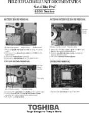
FIELD REPLACEABLE UNIT DOCUMENTATION Satellite Prom" 4600 Series BATTERY BOARD REMOVAL ANTENNA INTERFACE BOARD REMOVAL 1.12.5,5 bnee Pol.2.5.6 brass screws Plastic bra. Remove two WI2.5x6 brass screws securing the plastic 2. out the battery board assembly d Remove the battery board from P.I810 on top of the CPU TOSHIBA Tough Enough for Today's World bOwriEntcl m!Idle battery board cable from the plastic brims. COOLING MODULE REMOVAL Antenna interface board CoaNial cables P' jsleronn gean::::ntracatoa'rc r'n '11...
FIELD REPLACEABLE UNIT DOCUMENTATION Satellite Prom" 4600 Series BATTERY BOARD REMOVAL ANTENNA INTERFACE BOARD REMOVAL 1.12.5,5 bnee Pol.2.5.6 brass screws Plastic bra. Remove two WI2.5x6 brass screws securing the plastic 2. out the battery board assembly d Remove the battery board from P.I810 on top of the CPU TOSHIBA Tough Enough for Today's World bOwriEntcl m!Idle battery board cable from the plastic brims. COOLING MODULE REMOVAL Antenna interface board CoaNial cables P' jsleronn gean::::ntracatoa'rc r'n '11...
Replacement Instructions
Page 8
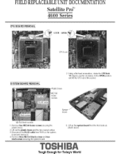
d TOSHIBA Tough Enough for Today's World IN.emtl iM noo comol cab. 3 Docomeo ine M.1.15 cable nomMI9 on ine symem boacl omove d. nxa Rol ne'l Own'rts"es "ys=c7Z. FIELD REPLACEABLE UNIT DOCUMENTATION Satellite Prci 4600 Series CPU BOARD REMOVAL • e LOCK OPEN ft ommy SYSTEM BOARD REMOVAL 2 Ville:it chi uulEki esrecriEge2OPPNPOVon 2:7 AR. rd bind 1 Remore..IRSN6 Mass sorewrs secumg the moot brace LM mi Me pl..
d TOSHIBA Tough Enough for Today's World IN.emtl iM noo comol cab. 3 Docomeo ine M.1.15 cable nomMI9 on ine symem boacl omove d. nxa Rol ne'l Own'rts"es "ys=c7Z. FIELD REPLACEABLE UNIT DOCUMENTATION Satellite Prci 4600 Series CPU BOARD REMOVAL • e LOCK OPEN ft ommy SYSTEM BOARD REMOVAL 2 Ville:it chi uulEki esrecriEge2OPPNPOVon 2:7 AR. rd bind 1 Remore..IRSN6 Mass sorewrs secumg the moot brace LM mi Me pl..
Replacement Instructions
Page 9
FIELD REPLACEABLE UNIT DOCUMENTATION Satellite Prom" 4600 Series IPSILED BOARD REMOVAL LED lens LED board M2x1 brass LEDISENSOR BOARD REMOVAL LoE.Drn'Zer LED sensci board LED board bracket IPS board 1 ,RoT rI,o,ve two 1.12a4 brass screws securing the IPS/LED 2 M1W Erm rdracket out of the LED lens antl lift r0aw me 1 Rernove . ree brms screw sec the LEINSanaor board. 2 Slide the LEO/Sensor board cable out or the top cover and on the LED/Sensor board TOSHIBA Tough Enough for Today's World
FIELD REPLACEABLE UNIT DOCUMENTATION Satellite Prom" 4600 Series IPSILED BOARD REMOVAL LED lens LED board M2x1 brass LEDISENSOR BOARD REMOVAL LoE.Drn'Zer LED sensci board LED board bracket IPS board 1 ,RoT rI,o,ve two 1.12a4 brass screws securing the IPS/LED 2 M1W Erm rdracket out of the LED lens antl lift r0aw me 1 Rernove . ree brms screw sec the LEINSanaor board. 2 Slide the LEO/Sensor board cable out or the top cover and on the LED/Sensor board TOSHIBA Tough Enough for Today's World
Replacement Instructions
Page 10
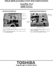
... the LCD cover 4. Carefully rohte the LCD module from Cf11 a. securing the display mask fatefully inset, put fingets between Pe display mask and Me L. bras. separate the TOSHIBA Tough Enough for Today's World Me flve latches en the right and left sides, ending with the els bottom latches LCDF inveite cable 2,1 FL cable FL inverter board 1. FIELD REPLACEABLE UNIT DOCUMENTATION Satellite' 4600 Series 14...
... the LCD cover 4. Carefully rohte the LCD module from Cf11 a. securing the display mask fatefully inset, put fingets between Pe display mask and Me L. bras. separate the TOSHIBA Tough Enough for Today's World Me flve latches en the right and left sides, ending with the els bottom latches LCDF inveite cable 2,1 FL cable FL inverter board 1. FIELD REPLACEABLE UNIT DOCUMENTATION Satellite' 4600 Series 14...
Replacement Instructions
Page 11
... latches screw 'aTZta FL cable . 6 brass FLInv rter.a. FIELD REPLACEABLE UNIT DOCUMENTATION Satellite' 4600 Series 15" DISPLAY MASK REMOVAL e el es et I O.h FL INVERTER AND 15" LCD REMOVAL LCD module III seals ° Mask seals 1 Remove nvo mask seals at. brass scream 3 There men secuung M- MsglaY mask Carefully insert your hngem Ibe display mask fndMe LCD module a. c.,n 'he latches staffing rom me top six latches lo...
... latches screw 'aTZta FL cable . 6 brass FLInv rter.a. FIELD REPLACEABLE UNIT DOCUMENTATION Satellite' 4600 Series 15" DISPLAY MASK REMOVAL e el es et I O.h FL INVERTER AND 15" LCD REMOVAL LCD module III seals ° Mask seals 1 Remove nvo mask seals at. brass scream 3 There men secuung M- MsglaY mask Carefully insert your hngem Ibe display mask fndMe LCD module a. c.,n 'he latches staffing rom me top six latches lo...


