User Manual
Page 30
... Removing a PC Card 142 Setting up a PC Card for your computer .........143 Using the Bridge Media Adapter Slot 143 Inserting memory media 144 Removing memory media 144 Using the i.LINK® port 145 Chapter 5: Toshiba Utilities 146 TOSHIBA Assist 147 Connect 148 Secure 149 Protect & Fix 150 Optimize 151 Setting passwords 152 Using an instant...
... Removing a PC Card 142 Setting up a PC Card for your computer .........143 Using the Bridge Media Adapter Slot 143 Inserting memory media 144 Removing memory media 144 Using the i.LINK® port 145 Chapter 5: Toshiba Utilities 146 TOSHIBA Assist 147 Connect 148 Secure 149 Protect & Fix 150 Optimize 151 Setting passwords 152 Using an instant...
User Manual
Page 53
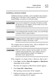
... while the computer is in good condition. If this procedure. The computer has two memory slots-Slot A and Slot B. If you use a small Phillips screwdriver that is in the memory module slots on may damage the computer, the module, or both. otherwise, skip to step 3. 1 Click Start, and then Turn off... the computer. 3 Unplug and remove any cables connected to room temperature before you install or remove a memory module, turn off computer...
... while the computer is in good condition. If this procedure. The computer has two memory slots-Slot A and Slot B. If you use a small Phillips screwdriver that is in the memory module slots on may damage the computer, the module, or both. otherwise, skip to step 3. 1 Click Start, and then Turn off... the computer. 3 Unplug and remove any cables connected to room temperature before you install or remove a memory module, turn off computer...
User Manual
Page 54
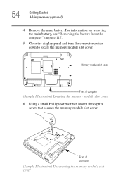
Front of computer (Sample Illustration) Locating the memory module slot cover 6 Using a small Phillips screwdriver, loosen the captive screw that secures the memory module slot cover. For information on removing the main battery, see "Removing the battery from the computer" on page 117. 5 Close the display panel and turn the computer upside down to locate the memory module slot cover. 54 Getting Started Adding memory (optional) 4 Remove the main battery. Memory module slot cover Front of computer (Sample Illustration) Unscrewing the memory module slot cover
Front of computer (Sample Illustration) Locating the memory module slot cover 6 Using a small Phillips screwdriver, loosen the captive screw that secures the memory module slot cover. For information on removing the main battery, see "Removing the battery from the computer" on page 117. 5 Close the display panel and turn the computer upside down to locate the memory module slot cover. 54 Getting Started Adding memory (optional) 4 Remove the main battery. Memory module slot cover Front of computer (Sample Illustration) Unscrewing the memory module slot cover

User Manual
Page 55
... screw and cover in a safe place so that you can damage the memory module. NOTE If your system has the memory modules stacked on page 58. NOTE If no memory slot is available, you may cause memory access problems. 9 Carefully remove the new memory module from its antistatic packaging, without touching its connector. 10 Locate an...
... screw and cover in a safe place so that you can damage the memory module. NOTE If your system has the memory modules stacked on page 58. NOTE If no memory slot is available, you may cause memory access problems. 9 Carefully remove the new memory module from its antistatic packaging, without touching its connector. 10 Locate an...

User Manual
Page 56
56 Getting Started Adding memory (optional) 11 Pick up the memory module by its connector. notch latch connector latch key (Sample Illustration) Aligning the memory module with its sides, avoiding any contact with the socket 12 Firmly press the memory module into the memory slot's socket at approximately a 30-degree angle (to the horizontal surface of the computer). (Sample Illustration) Inserting the memory module into the socket Position the module toward the socket, aligning the connector's notch with the matching key in the socket.
56 Getting Started Adding memory (optional) 11 Pick up the memory module by its connector. notch latch connector latch key (Sample Illustration) Aligning the memory module with its sides, avoiding any contact with the socket 12 Firmly press the memory module into the memory slot's socket at approximately a 30-degree angle (to the horizontal surface of the computer). (Sample Illustration) Inserting the memory module into the socket Position the module toward the socket, aligning the connector's notch with the matching key in the socket.

User Manual
Page 57
... should "snap" into place securely with the corresponding cutouts in place. If the latches and cutouts do not line up correctly, repeat steps 12-13. Memory slots Front of the socket. latch latch (Sample Illustration) Pressing down on the top edge of the module to seat the module into the latches at...
... should "snap" into place securely with the corresponding cutouts in place. If the latches and cutouts do not line up correctly, repeat steps 12-13. Memory slots Front of the socket. latch latch (Sample Illustration) Pressing down on the top edge of the module to seat the module into the latches at...
User Manual
Page 58
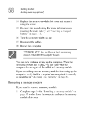
... the computer has recognized it using the screw. 15 Re-insert the main battery. 58 Getting Started Adding memory (optional) 14 Replace the memory module slot cover and secure it correctly as described in "Installing a memory module" on page 53 to work. When the operating system has loaded, you can now continue setting up...
... the computer has recognized it using the screw. 15 Re-insert the main battery. 58 Getting Started Adding memory (optional) 14 Replace the memory module slot cover and secure it correctly as described in "Installing a memory module" on page 53 to work. When the operating system has loaded, you can now continue setting up...
User Manual
Page 59
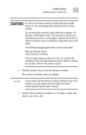
... following message appears when you turn on the power: Warning: Resume Failure Press Any Key to a 30-degree angle and slide it out of the slot. The following : Press the power button and hold it down for at least ten seconds, then turn the power on and data in Standby or... Hibernation mode. The memory module pops up slightly. Do not remove the memory module while the computer is in memory will not be lost. In either of the above cases, the Standby configuration will be saved. You can...
... following message appears when you turn on the power: Warning: Resume Failure Press Any Key to a 30-degree angle and slide it out of the slot. The following : Press the power button and hold it down for at least ten seconds, then turn the power on and data in Standby or... Hibernation mode. The memory module pops up slightly. Do not remove the memory module while the computer is in memory will not be lost. In either of the above cases, the Standby configuration will be saved. You can...
User Manual
Page 60
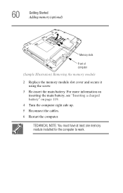
60 Getting Started Adding memory (optional) Memory slots Front of computer (Sample Illustration) Removing the memory module 2 Replace the memory module slot cover and secure it using the screw. 3 Re-insert the main battery. For more information on inserting the main battery, see "Inserting a charged battery" on page 119. 4 Turn the computer right side up. 5 Reconnect the cables. 6 Restart the computer. TECHNICAL NOTE: You must have at least one memory module installed for the computer to work.
60 Getting Started Adding memory (optional) Memory slots Front of computer (Sample Illustration) Removing the memory module 2 Replace the memory module slot cover and secure it using the screw. 3 Re-insert the main battery. For more information on inserting the main battery, see "Inserting a charged battery" on page 119. 4 Turn the computer right side up. 5 Reconnect the cables. 6 Restart the computer. TECHNICAL NOTE: You must have at least one memory module installed for the computer to work.

User Manual
Page 61
If the computer does not recognize the memory configuration, turn off the computer, remove the memory slot cover, and check that the module is sensitive to touch and enables you to move your finger several times across the TouchPad in the direction ... Start, Control Panel, Performance and Maintenance, and then System. 2 The General tab view automatically appears and shows total memory. Getting Started Using the TouchPad™ 61 Checking total memory When you add or remove a memory module, you would like to move the cursor: ❖ To move the cursor to the top of the...
If the computer does not recognize the memory configuration, turn off the computer, remove the memory slot cover, and check that the module is sensitive to touch and enables you to move your finger several times across the TouchPad in the direction ... Start, Control Panel, Performance and Maintenance, and then System. 2 The General tab view automatically appears and shows total memory. Getting Started Using the TouchPad™ 61 Checking total memory When you add or remove a memory module, you would like to move the cursor: ❖ To move the cursor to the top of the...
User Manual
Page 143
... on certain models) The Bridge Media Adapter slot (available on certain models) supports the use as soon as hard disk cards, network cards, and SCSI adapters, may also support other types of supported media, visit Toshiba's Web site at accessories.toshiba.com. These media can be set up your PC ...: digital music players, cellular phones, PDAs, digital cameras, digital video camcorders, etc. NOTE Do not use the drag-and-drop feature of Memory Stick™, Memory Stick™ PRO, Secure Digital™ (SD™), MMC™ (MultiMediaCard™), or xD-Picture Card™ media.
... on certain models) The Bridge Media Adapter slot (available on certain models) supports the use as soon as hard disk cards, network cards, and SCSI adapters, may also support other types of supported media, visit Toshiba's Web site at accessories.toshiba.com. These media can be set up your PC ...: digital music players, cellular phones, PDAs, digital cameras, digital video camcorders, etc. NOTE Do not use the drag-and-drop feature of Memory Stick™, Memory Stick™ PRO, Secure Digital™ (SD™), MMC™ (MultiMediaCard™), or xD-Picture Card™ media.
User Manual
Page 144
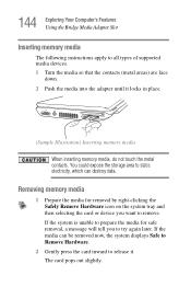
Removing memory media 1 Prepare the media for safe removal, a message will tell you want to remove. If the system is unable to prepare the media for removal .... 2 Gently press the card inward to release it locks in place. (Sample Illustration) Inserting memory media When inserting memory media, do not touch the metal contacts. 144 Exploring Your Computer's Features Using the Bridge Media Adapter Slot Inserting memory media The following instructions apply to all types of supported media devices. 1 Turn the media...
Removing memory media 1 Prepare the media for safe removal, a message will tell you want to remove. If the system is unable to prepare the media for removal .... 2 Gently press the card inward to release it locks in place. (Sample Illustration) Inserting memory media When inserting memory media, do not touch the metal contacts. 144 Exploring Your Computer's Features Using the Bridge Media Adapter Slot Inserting memory media The following instructions apply to all types of supported media devices. 1 Turn the media...
User Manual
Page 163
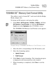
...❖ Full Format 4 Click Start to exit the utility. To format an SD memory card using this utility: 1 Click Start, All Programs, Toshiba, Utilities, and then SD Memory Card Format, or click the SD Memory Card icon in the window. 5 When formatting is completed, click Close to begin ...formatting. The formatting progress is used to format SD™ cards used with the Bridge Media Adapter slot. 163 Toshiba Utilities TOSHIBA SD™ Memory Card Format Utility TOSHIBA SD™ Memory Card Format Utility This utility is displayed in the horizontal bar in the Optimize tab of...
...❖ Full Format 4 Click Start to exit the utility. To format an SD memory card using this utility: 1 Click Start, All Programs, Toshiba, Utilities, and then SD Memory Card Format, or click the SD Memory Card icon in the window. 5 When formatting is completed, click Close to begin ...formatting. The formatting progress is used to format SD™ cards used with the Bridge Media Adapter slot. 163 Toshiba Utilities TOSHIBA SD™ Memory Card Format Utility TOSHIBA SD™ Memory Card Format Utility This utility is displayed in the horizontal bar in the Optimize tab of...
User Manual
Page 181
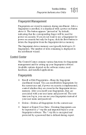
... . Control Center The Control Center contains various functions for fingerprint management and for setting up to use your fingerprints instead of slots remaining is defined during enrollment. Available options depend on the software status, used for the current user. ❖ Import or ...delete fingerprints for logon, click the Boot button to your fingerprints, they are stored in the fingerprint device memory. 181 Toshiba Utilities Fingerprint Authentication Utility Fingerprint Management Fingerprints are stored in the enrollment wizard. You can typically hold up your...
... . Control Center The Control Center contains various functions for fingerprint management and for setting up to use your fingerprints instead of slots remaining is defined during enrollment. Available options depend on the software status, used for the current user. ❖ Import or ...delete fingerprints for logon, click the Boot button to your fingerprints, they are stored in the fingerprint device memory. 181 Toshiba Utilities Fingerprint Authentication Utility Fingerprint Management Fingerprints are stored in the enrollment wizard. You can typically hold up your...
User Manual
Page 212
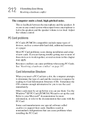
PC Card problems PC Cards (PCMCIA-compatible) include many types of new cards. If you insert a PC Card into a slot, the computer attempts to determine the type of these devices to support their cards. Use the Windows® XP PC Card (PCMCIA) Wizard ... and the speaker volume is too loud. Most PC Card problems occur during installation and setup of devices, such as a removable hard disk, additional memory, or a pager. Resource conflicts can use special software called enablers to work together, several sections in nonstandard configurations that came with the PC Card....
PC Card problems PC Cards (PCMCIA-compatible) include many types of new cards. If you insert a PC Card into a slot, the computer attempts to determine the type of these devices to support their cards. Use the Windows® XP PC Card (PCMCIA) Wizard ... and the speaker volume is too loud. Most PC Card problems occur during installation and setup of devices, such as a removable hard disk, additional memory, or a pager. Resource conflicts can use special software called enablers to work together, several sections in nonstandard configurations that came with the PC Card....

User Manual
Page 283
... settings not working with hardware 207 program has performed an illegal operation 192 warning resume failure 193 Error-checking 208 Ethernet LAN port 133 expansion memory slot 55 exploring the desktop 125 external monitor not working 207 mouse 67 external diskette drive connecting 69 external display, adjusting 66 F FAT (File Allocation Table... I i.LINK port 145 icon 126, 127 desktop 127 Internet Explorer 127 moving to desktop 126 recycle bin 127 safety 36 Windows Media Player 127 installation memory module 53 installing memory modules 52 mouse 67 instant passwords, using 152
... settings not working with hardware 207 program has performed an illegal operation 192 warning resume failure 193 Error-checking 208 Ethernet LAN port 133 expansion memory slot 55 exploring the desktop 125 external monitor not working 207 mouse 67 external diskette drive connecting 69 external display, adjusting 66 F FAT (File Allocation Table... I i.LINK port 145 icon 126, 127 desktop 127 Internet Explorer 127 moving to desktop 126 recycle bin 127 safety 36 Windows Media Player 127 installation memory module 53 installing memory modules 52 mouse 67 instant passwords, using 152
User Manual
Page 284
... 83 Windows special keys 85 keyboard, external 66 keyboard, full-size 83 L lock computer, using 80 M main battery removing 117 memory adding 52 problem solving 202 removing expansion slot cover 55 memory module inserting 56 installation 53 removing 60 microphone 139 modem connecting to telephone line 130 determining COM port 129 problem solving...
... 83 Windows special keys 85 keyboard, external 66 keyboard, full-size 83 L lock computer, using 80 M main battery removing 117 memory adding 52 problem solving 202 removing expansion slot cover 55 memory module inserting 56 installation 53 removing 60 microphone 139 modem connecting to telephone line 130 determining COM port 129 problem solving...
User Manual
Page 286
... 211 non-system disk or disk error 194, 210 PC Card 212 checklist 213 error occurs 215 hot swapping fails 214 not recognized 214 slot appears dead 213 power and batteries 202 printer 215, 216 program not responding 190 program not working properly 209 screen does not look right/... blank 205 does not look normal/flickers 206 secondary button 62 set up communications 128 setting up adding memory 52 computer 43, 53 TOSHIBA Touch and Launch 175 setting up a connection 132 settings TOSHIBA Touch and Launch 175 sound problem solving 211 sounds recording 138 speakers using external 140 Standby mode 72...
... 211 non-system disk or disk error 194, 210 PC Card 212 checklist 213 error occurs 215 hot swapping fails 214 not recognized 214 slot appears dead 213 power and batteries 202 printer 215, 216 program not responding 190 program not working properly 209 screen does not look right/... blank 205 does not look normal/flickers 206 secondary button 62 set up communications 128 setting up adding memory 52 computer 43, 53 TOSHIBA Touch and Launch 175 setting up a connection 132 settings TOSHIBA Touch and Launch 175 sound problem solving 211 sounds recording 138 speakers using external 140 Standby mode 72...


