User Guide
Page 53
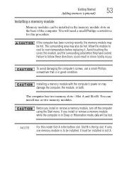
... remove a memory module, turn off the computer using the Start menu. Slot B is the top slot. The surrounding area may damage the computer, the module, or both. Failure to room temperature before they have cooled. Avoid touching the cover, the module, and the surrounding area before replacing it must be hot. Before you install or remove a memory module while the computer is in minor bodily injury. Getting Started 53 Adding memory (optional) Installing a memory module Memory modules...
... remove a memory module, turn off the computer using the Start menu. Slot B is the top slot. The surrounding area may damage the computer, the module, or both. Failure to room temperature before they have cooled. Avoid touching the cover, the module, and the surrounding area before replacing it must be hot. Before you install or remove a memory module while the computer is in minor bodily injury. Getting Started 53 Adding memory (optional) Installing a memory module Memory modules...

User Guide
Page 58
... the computer and open the memory module slot cover. The computer could hang up the computer. 58 Getting Started Adding memory (optional) 15 Re-insert the main battery. For more information on inserting the main battery, see "Inserting a charged battery" on . If you need to remove a memory module: 1 Complete steps 1-8 in Sleep or Hibernation mode. Removing a memory module If you are adding extra memory after setting up . 17 Reconnect the cables. 18 Restart the...
... the computer and open the memory module slot cover. The computer could hang up the computer. 58 Getting Started Adding memory (optional) 15 Re-insert the main battery. For more information on inserting the main battery, see "Inserting a charged battery" on . If you need to remove a memory module: 1 Complete steps 1-8 in Sleep or Hibernation mode. Removing a memory module If you are adding extra memory after setting up . 17 Reconnect the cables. 18 Restart the...

User Guide
Page 60
... memory (optional) 4 Replace the memory module slot cover and secure it using the screw. 5 Re-insert the main battery. If you can check that says, "Windows® needs your permission. TECHNICAL NOTE: You must have at least one memory module installed for the computer to continue." For more information on inserting the main battery, see "Inserting a charged battery" on page 53), and then check that the module is displayed...
... memory (optional) 4 Replace the memory module slot cover and secure it using the screw. 5 Re-insert the main battery. If you can check that says, "Windows® needs your permission. TECHNICAL NOTE: You must have at least one memory module installed for the computer to continue." For more information on inserting the main battery, see "Inserting a charged battery" on page 53), and then check that the module is displayed...

User Guide
Page 69
... TouchPad™ The TouchPad™ is enabled by either double-tapping the TouchPad or clicking the control buttons. This feature can be disabled or changed in the Mouse Properties dialog box. Scrolling with any wheel device on page 210. The function of the TouchPad. Getting Started 69 Using external display devices Once you have positioned your cursor, you can click it uses the right mouse button. Control buttons When a step instructs you are two active...
... TouchPad™ The TouchPad™ is enabled by either double-tapping the TouchPad or clicking the control buttons. This feature can be disabled or changed in the Mouse Properties dialog box. Scrolling with any wheel device on page 210. The function of the TouchPad. Getting Started 69 Using external display devices Once you have positioned your cursor, you can click it uses the right mouse button. Control buttons When a step instructs you are two active...

User Guide
Page 70
... Started Using external display devices ❖ An external monitor or projector via the RGB (monitor) Out port S-video Out port* RGB (Monitor Out) port (Sample Illustration) Back of the computer. 3 Connect the device's power cable to a live electrical outlet. 4 Turn on certain models You cannot connect both the S-video Out port and the HDMI Out port to the same device at the factory to S-video Out. To do this: 1 Read the directions that came with display options. 5 Select the settings...
... Started Using external display devices ❖ An external monitor or projector via the RGB (monitor) Out port S-video Out port* RGB (Monitor Out) port (Sample Illustration) Back of the computer. 3 Connect the device's power cable to a live electrical outlet. 4 Turn on certain models You cannot connect both the S-video Out port and the HDMI Out port to the same device at the factory to S-video Out. To do this: 1 Read the directions that came with display options. 5 Select the settings...

User Guide
Page 71
... certain models) HDMI™-CEC (Consumer Electronics Control) is selected using the Fn+F5 key. ❖ Switch the video output (HDMI or LCD) when executing certain desktop icons. ❖ Enable/Disable the HDMI-CEC function on . Directing the display output when you turn on the computer Once you have connected an external display device, you can allow you want takes effect. For more detailed HDMI-CEC information, visit pcsupport.toshiba.com...
... certain models) HDMI™-CEC (Consumer Electronics Control) is selected using the Fn+F5 key. ❖ Switch the video output (HDMI or LCD) when executing certain desktop icons. ❖ Enable/Disable the HDMI-CEC function on . Directing the display output when you turn on the computer Once you have connected an external display device, you can allow you want takes effect. For more detailed HDMI-CEC information, visit pcsupport.toshiba.com...

User Guide
Page 154
...-This function restores the computer from Sleep Mode depending on the external devices connected to Disabled. change the setting to use the "USB Wakeup function," attach the mouse or keyboard to Mode-1. 154 Utilities TOSHIBA Hardware Setup Metal paper clips or hair pins/clips will not work. If you want to use this happens, change the "USB Sleep and Charge function" setting to the USB ports. Any options that appear in TOSHIBA Hardware Setup, the "USB Wakeup function" does not work with USB ports. USB Sleep and Charge function Settings-The default setting is Enabled in...
...-This function restores the computer from Sleep Mode depending on the external devices connected to Disabled. change the setting to use the "USB Wakeup function," attach the mouse or keyboard to Mode-1. 154 Utilities TOSHIBA Hardware Setup Metal paper clips or hair pins/clips will not work. If you want to use this happens, change the "USB Sleep and Charge function" setting to the USB ports. Any options that appear in TOSHIBA Hardware Setup, the "USB Wakeup function" does not work with USB ports. USB Sleep and Charge function Settings-The default setting is Enabled in...
User Guide
Page 170
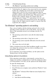
... some way such as installing a new program or adding a device. The Windows® operating system is the correct unit for your system's configuration or verify the startup procedure to start . ❖ The operating system responds differently from an AC adaptor that is rated for each device. Using Startup options to fix problems If the operating system fails to fix the problem. Unless a hardware device has failed, problems usually occur when you...
... some way such as installing a new program or adding a device. The Windows® operating system is the correct unit for your system's configuration or verify the startup procedure to start . ❖ The operating system responds differently from an AC adaptor that is rated for each device. Using Startup options to fix problems If the operating system fails to fix the problem. Unless a hardware device has failed, problems usually occur when you...
User Guide
Page 174
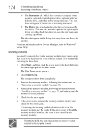
... about Device Manager, refer to the monitor, optional external optical drive, optional external diskette drive, and other power-using resources. ❖ The Driver tab, which lists resources assigned to Windows® online Help. The computer shuts down completely. 3 Remove the memory module, following the instructions in "Removing a memory module" on page 53, and making sure the module is worthwhile checking for these first: 1 Click Start, and then click the arrow next to the Lock button in...
... about Device Manager, refer to the monitor, optional external optical drive, optional external diskette drive, and other power-using resources. ❖ The Driver tab, which lists resources assigned to Windows® online Help. The computer shuts down completely. 3 Remove the memory module, following the instructions in "Removing a memory module" on page 53, and making sure the module is worthwhile checking for these first: 1 Click Start, and then click the arrow next to the Lock button in...
User Guide
Page 222
... create a complete screen image. See also cache, CPU cache, L2 cache. When you turn the computer off . internal device - Compare non-interlaced. See also World Wide Web. The decentralized, world-wide network of data. See also Sleep, Suspend. A small image displayed on the motherboard to perform a task instead of using a pointing device such as the battery save mode. (2) A key or combination of computers or other services...
... create a complete screen image. See also cache, CPU cache, L2 cache. When you turn the computer off . internal device - Compare non-interlaced. See also World Wide Web. The decentralized, world-wide network of data. See also Sleep, Suspend. A small image displayed on the motherboard to perform a task instead of using a pointing device such as the battery save mode. (2) A key or combination of computers or other services...
User Guide
Page 228
... charge indicator light 49, 109 charge not lasting 176 charging 47, 49 conserving power 112 disposal 120 low charge 111 monitoring power 49, 109 not charging 175 228 notifications 111 power plan 204 power plan hot key 114 real-time clock (RTC) 106 removing 115 BIOS Setup see TOSHIBA Hardware Setup Bridge Media Adapter inserting memory media 134 removing memory media 135 button power 52, 62 start 124 C CD, using 97 character keys 89 charging the battery 49 checking device properties 173 click 69 communications network connection...
... charge indicator light 49, 109 charge not lasting 176 charging 47, 49 conserving power 112 disposal 120 low charge 111 monitoring power 49, 109 not charging 175 228 notifications 111 power plan 204 power plan hot key 114 real-time clock (RTC) 106 removing 115 BIOS Setup see TOSHIBA Hardware Setup Bridge Media Adapter inserting memory media 134 removing memory media 135 button power 52, 62 start 124 C CD, using 97 character keys 89 charging the battery 49 checking device properties 173 click 69 communications network connection...

User Guide
Page 229
... DVD, using 97 E error messages device driver conflict 172 general hardware problem 172 non-system disk or disk error 169 problem with display settings/ current settings not working with hardware 178 warning resume failure 168 Error-checking 179 exploring the desktop 122 ExpressCard® checklist 182 computer stops working 183 errors 184 hot swapping fails 183 inserting 133 not recognized 184 problem solving 182, 183 removing 133 external monitor not working 178 mouse 73 external diskette drive connecting 74 external display, adjusting...
... DVD, using 97 E error messages device driver conflict 172 general hardware problem 172 non-system disk or disk error 169 problem with display settings/ current settings not working with hardware 178 warning resume failure 168 Error-checking 179 exploring the desktop 122 ExpressCard® checklist 182 computer stops working 183 errors 184 hot swapping fails 183 inserting 133 not recognized 184 problem solving 182, 183 removing 133 external monitor not working 178 mouse 73 external diskette drive connecting 74 external display, adjusting...
User Guide
Page 231
... memory module slot 55 microphone 130 modem connecting to telephone line 126 problem solving 185 monitor 69 connecting 70 not working 177 mouse installing 73 mouse utility 150 N network accessing 126 Connect to the Internet 126 networking wireless 125 Notification Area 124 O Opening the display panel 50 optical disc positioning 100 optical discs handling 100 inserting 99 removing 102 optical drive problems 180 troubleshooting 180 using 97 optical media recording 101 other documentation 40 overlay keys 91 P password deleting a supervisor 146 disabling a user 147 setting a user...
... memory module slot 55 microphone 130 modem connecting to telephone line 126 problem solving 185 monitor 69 connecting 70 not working 177 mouse installing 73 mouse utility 150 N network accessing 126 Connect to the Internet 126 networking wireless 125 Notification Area 124 O Opening the display panel 50 optical disc positioning 100 optical discs handling 100 inserting 99 removing 102 optical drive problems 180 troubleshooting 180 using 97 optical media recording 101 other documentation 40 overlay keys 91 P password deleting a supervisor 146 disabling a user 147 setting a user...

User Guide
Page 232
... 182 error occurs 184 hot swapping fails 183 not recognized 184 slot appears dead 183 external display not working 178 external monitor 177 faulty memory 174 hardware conflict 172 high-pitched noise 182 Internet bookmarked site not found 171 Internet connection is slow 171 keyboard not responding 168 missing files/trouble accessing a disk 179 modem not receiving or transmitting 185 no sound 182 non-system disk or disk error 169 power and batteries...
... 182 error occurs 184 hot swapping fails 183 not recognized 184 slot appears dead 183 external display not working 178 external monitor 177 faulty memory 174 hardware conflict 172 high-pitched noise 182 Internet bookmarked site not found 171 Internet connection is slow 171 keyboard not responding 168 missing files/trouble accessing a disk 179 modem not receiving or transmitting 185 no sound 182 non-system disk or disk error 169 power and batteries...
User Guide
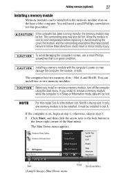
Page 27
... touching the cover, the module, and the surrounding area before replacing it must be lost. The computer has two memory slots-Slot A and Slot B. Installing a memory module with the computer's power on may be hot. Slot B is in good condition. To avoid damaging the computer's screws, use a small Phillips screwdriver that is the top slot. You can be installed, it . If you install or remove a memory module, turn off the computer using the Start menu...
... touching the cover, the module, and the surrounding area before replacing it must be lost. The computer has two memory slots-Slot A and Slot B. Installing a memory module with the computer's power on may be hot. Slot B is in good condition. To avoid damaging the computer's screws, use a small Phillips screwdriver that is the top slot. You can be installed, it . If you install or remove a memory module, turn off the computer using the Start menu...
User Guide
Page 31
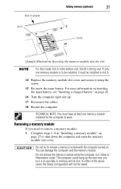
... and open the memory module slot cover. Do not try to remove a memory module with the computer turned on and data in slot A. 14 Replace the memory module slot cover and secure it must have at least one memory module is in "Installing a memory module" on page 27 to be installed, it using the screw. 15 Re-insert the main battery. In either of computer Slot A Adding memory (optional) 31 Slot B (Sample Illustration) Inserting the memory module into the slot...
... and open the memory module slot cover. Do not try to remove a memory module with the computer turned on and data in slot A. 14 Replace the memory module slot cover and secure it must have at least one memory module is in "Installing a memory module" on page 27 to be installed, it using the screw. 15 Re-insert the main battery. In either of computer Slot A Adding memory (optional) 31 Slot B (Sample Illustration) Inserting the memory module into the slot...

User Guide
Page 32
... power: If "Start Windows® Normally" is highlighted, then press Enter. TECHNICAL NOTE: You must remove the top module first before removing/installing the bottom module. 3 Gently lift the memory module to a 30-degree angle and slide it out of the Safe Mode options is highlighted, it using the screw. 5 Re-insert the main battery. If one another, you turn on top of one of the slot. 4 Replace the memory module slot cover...
... power: If "Start Windows® Normally" is highlighted, then press Enter. TECHNICAL NOTE: You must remove the top module first before removing/installing the bottom module. 3 Gently lift the memory module to a 30-degree angle and slide it out of the Safe Mode options is highlighted, it using the screw. 5 Re-insert the main battery. If one another, you turn on top of one of the slot. 4 Replace the memory module slot cover...

Maintenance Manual
Page 3
... This maintenance manual describes how to perform hardware service maintenance for the Toshiba Personal Computer Satellite A300/Satellite Pro A300/EQUIUM A300/SATEGO A300, referred to fasten screws securely with the right screwdriver. The procedures described in this manual are used in the field. SAFETY PRECAUTIONS Four types of a hazard that could result in death or serious bodily injury, if the safety instruction is not observed. Improper repair...
... This maintenance manual describes how to perform hardware service maintenance for the Toshiba Personal Computer Satellite A300/Satellite Pro A300/EQUIUM A300/SATEGO A300, referred to fasten screws securely with the right screwdriver. The procedures described in this manual are used in the field. SAFETY PRECAUTIONS Four types of a hazard that could result in death or serious bodily injury, if the safety instruction is not observed. Improper repair...
Maintenance Manual
Page 130
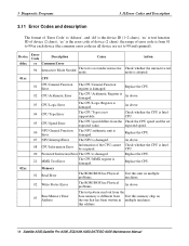
... base memory is the error code of device (2 chars); this address. 58 Satellite A300,Satellite Pro A300, EQUIUM A300,SATEGO A300 Maintenance Manual expected speed. 06 NPU General Function Error The NPU arithmetic unit is Intel be acquired. Replace the CPU. 21 MMX Test Error The CPU MMX register is Intel CPU. 05 CPU Speed Error The CPU speed differs from the Check the CPU speed and the set to 99 in each device (the common error codes...
... base memory is the error code of device (2 chars); this address. 58 Satellite A300,Satellite Pro A300, EQUIUM A300,SATEGO A300 Maintenance Manual expected speed. 06 NPU General Function Error The NPU arithmetic unit is Intel be acquired. Replace the CPU. 21 MMX Test Error The CPU MMX register is Intel CPU. 05 CPU Speed Error The CPU speed differs from the Check the CPU speed and the set to 99 in each device (the common error codes...

Maintenance Manual
Page 133
... method Card Please update other method net card or use Keyboard Satellite A300,Satellite Pro A300, EQUIUM A300,SATEGO A300 Maintenance Manual 61 Check and see whether the AGP video card has any physical problem with the video Check and see whether the monitor has any physical problem. 26 8bits Video Mode Test Error As above. As above . Replace the LCD. 19 Register Test Error Physical problems with the video card or the monitor. 16 AGP Test Error AGP configuration register errors. the video...
... method Card Please update other method net card or use Keyboard Satellite A300,Satellite Pro A300, EQUIUM A300,SATEGO A300 Maintenance Manual 61 Check and see whether the AGP video card has any physical problem with the video Check and see whether the monitor has any physical problem. 26 8bits Video Mode Test Error As above. As above . Replace the LCD. 19 Register Test Error Physical problems with the video card or the monitor. 16 AGP Test Error AGP configuration register errors. the video...


