
Maintenance Manual
Page 8
Chapter 4 Replacement Procedures 4.1 Overview...4-1 4.2 Battery pack ...4-8 4.3 PC card...4-10 4.4 Memory module B 4-11 4.5 HDD...4-13 4.6 Keyboard...4-17 4.7 Memory module A 4-21 4.8 Cover assembly and Base assembly 4-23 4.9 Base latch ...4-26 4.10 Front panel/Microphone 4-27 4.11 Bluetooth module...4-33 4.12 ...
Chapter 4 Replacement Procedures 4.1 Overview...4-1 4.2 Battery pack ...4-8 4.3 PC card...4-10 4.4 Memory module B 4-11 4.5 HDD...4-13 4.6 Keyboard...4-17 4.7 Memory module A 4-21 4.8 Cover assembly and Base assembly 4-23 4.9 Base latch ...4-26 4.10 Front panel/Microphone 4-27 4.11 Bluetooth module...4-33 4.12 ...

Maintenance Manual
Page 43
...3 Connection Check 2-12 Procedure 4 Charge Check 2-13 Procedure 5 Replacement Check 2-14 2.4 System Board Troubleshooting 2-15 Procedure 1 Message Check ...Replacement Check 2-34 2.6 HDD Troubleshooting 2-35 Procedure 1 Message Check 2-35 Procedure 2 Partition Check 2-36 Procedure 3 Format Check 2-37 Procedure 4 Diagnostic Test Program Execution Check 2-38 Procedure 5 Connector Check and Replacement Check 2-39 2.7 Keyboard and Dual point Troubleshooting 2-40 Procedure 1 Diagnostic Test Program Execution Check 2-40 Procedure 2 Connector Check and Replacement Check 2-41 PORTEGE R500...
...3 Connection Check 2-12 Procedure 4 Charge Check 2-13 Procedure 5 Replacement Check 2-14 2.4 System Board Troubleshooting 2-15 Procedure 1 Message Check ...Replacement Check 2-34 2.6 HDD Troubleshooting 2-35 Procedure 1 Message Check 2-35 Procedure 2 Partition Check 2-36 Procedure 3 Format Check 2-37 Procedure 4 Diagnostic Test Program Execution Check 2-38 Procedure 5 Connector Check and Replacement Check 2-39 2.7 Keyboard and Dual point Troubleshooting 2-40 Procedure 1 Diagnostic Test Program Execution Check 2-40 Procedure 2 Connector Check and Replacement Check 2-41 PORTEGE R500...
Maintenance Manual
Page 62
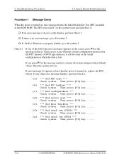
Then the system reboots. If any other error message displays, perform Check 2. (a) *** Bad HDD type *** Check system. Then press [F1] key ...... (d) *** Bad memory size *** Check system. Then press [F1] key ...... (e) *** Bad time function *** Check system. Then press [F1] key ...... (g) *** ... or Windows is turned on the screen, press F1 as the message instructs, returns all system settings to Procedure 3. Then press [F1] key ...... 2-16 [CONFIDENTIAL] PORTEGE R500 Maintenance Manual (960-634) Check 1 If one of the following error messages appears on , replace the RTC battery.
Then the system reboots. If any other error message displays, perform Check 2. (a) *** Bad HDD type *** Check system. Then press [F1] key ...... (d) *** Bad memory size *** Check system. Then press [F1] key ...... (e) *** Bad time function *** Check system. Then press [F1] key ...... (g) *** ... or Windows is turned on the screen, press F1 as the message instructs, returns all system settings to Procedure 3. Then press [F1] key ...... 2-16 [CONFIDENTIAL] PORTEGE R500 Maintenance Manual (960-634) Check 1 If one of the following error messages appears on , replace the RTC battery.

Maintenance Manual
Page 81
... procedures as instructed. If the following messages do not appear, perform Check 3. PORTEGE R500 Maintenance Manual (960-634) [CONFIDENTIAL] 2-35 If the problem still exists, go... 1 If any key when ready ..... 2.6 HDD Troubleshooting 2 Troubleshooting Procedures 2 2.6 HDD Troubleshooting This section describes how to determine if the HDD is set to not used , choose another ... 3: Format Check Procedure 4: Diagnostic Test Program Execution Check Procedure 5: Connector Check and Replacement Check CAUTION: The contents of the hard disk will disappear.) Check 2 If either of...
... procedures as instructed. If the following messages do not appear, perform Check 3. PORTEGE R500 Maintenance Manual (960-634) [CONFIDENTIAL] 2-35 If the problem still exists, go... 1 If any key when ready ..... 2.6 HDD Troubleshooting 2 Troubleshooting Procedures 2 2.6 HDD Troubleshooting This section describes how to determine if the HDD is set to not used , choose another ... 3: Format Check Procedure 4: Diagnostic Test Program Execution Check Procedure 5: Connector Check and Replacement Check CAUTION: The contents of the hard disk will disappear.) Check 2 If either of...
Maintenance Manual
Page 84
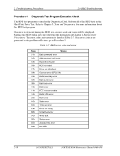
...exists, go to Chapter 3, Tests and Diagnostics, for more information about the HDD test program. If an error is detected during the HDD test, an error code and status will be displayed. Table 2-7 HDD error code and status Code 01h 02h 04h 05h 07h 08h 09h 0Ah ... out error Drive not ready Undefined error Write fault Status error Access time error No HDD 2-38 [CONFIDENTIAL] PORTEGE R500 Maintenance Manual (960-634) The error codes and statuses are listed in Chapter 4, Replacement Procedures. Replace the HDD with a new one following the instructions in Table 2-7. Perform all of the...
...exists, go to Chapter 3, Tests and Diagnostics, for more information about the HDD test program. If an error is detected during the HDD test, an error code and status will be displayed. Table 2-7 HDD error code and status Code 01h 02h 04h 05h 07h 08h 09h 0Ah ... out error Drive not ready Undefined error Write fault Status error Access time error No HDD 2-38 [CONFIDENTIAL] PORTEGE R500 Maintenance Manual (960-634) The error codes and statuses are listed in Chapter 4, Replacement Procedures. Replace the HDD with a new one following the instructions in Table 2-7. Perform all of the...

Maintenance Manual
Page 85
...a new one following the instructions in Chapter 4, Replacement Procedures. PORTEGE R500 Maintenance Manual (960-634) [CONFIDENTIAL] 2-39 Check 3 The HDD FPC may be damaged. Replace it with a new one following the instructions in Chapter 4, Replacement Procedures. Check 2 The HDD may be damaged. If the problem still exists, ... Check 2. If any of the connections are loose, reconnect firmly and repeat Procedure 1. Replace it with a new one following checks: Check 1 Make sure the HDD is still an error, go to CN1800 on the system board. Disassemble the computer following...
...a new one following the instructions in Chapter 4, Replacement Procedures. PORTEGE R500 Maintenance Manual (960-634) [CONFIDENTIAL] 2-39 Check 3 The HDD FPC may be damaged. Replace it with a new one following the instructions in Chapter 4, Replacement Procedures. Check 2 The HDD may be damaged. If the problem still exists, ... Check 2. If any of the connections are loose, reconnect firmly and repeat Procedure 1. Replace it with a new one following checks: Check 1 Make sure the HDD is still an error, go to CN1800 on the system board. Disassemble the computer following...
Maintenance Manual
Page 213
4 Replacement Procedures Chapter 4 Contents 4.1 General...4-1 4.2 Battery pack ...4-8 4.3 PC card...4-10 4.4 SD memory card ...4-11 4.5 Memory module...4-12 4.6 Base ... 4.10 CPU fan assembly...4-23 4.11 RTC battery...4-26 4.12 DC-IN jack...4-28 4.13 Bluetooth module...4-29 4.14 HDD/SSD ...4-31 4.14.1 2.5" HDD 4-32 4.14.2 1.8" HDD 4-33 4.14.3 SSD ...4-35 4.15 Sound board/Internal microphone 4-37 4.16 ODD/SD board...4-39 4.17 USB board...LCD unit ...4-59 4.24 Wireless LAN antenna/Bluetooth antenna 4-62 4.25 Hinge...4-64 PORTÉGÉ R500 Maintenance Manual (960-634) [CONFIDENTIAL] 4-iii
4 Replacement Procedures Chapter 4 Contents 4.1 General...4-1 4.2 Battery pack ...4-8 4.3 PC card...4-10 4.4 SD memory card ...4-11 4.5 Memory module...4-12 4.6 Base ... 4.10 CPU fan assembly...4-23 4.11 RTC battery...4-26 4.12 DC-IN jack...4-28 4.13 Bluetooth module...4-29 4.14 HDD/SSD ...4-31 4.14.1 2.5" HDD 4-32 4.14.2 1.8" HDD 4-33 4.14.3 SSD ...4-35 4.15 Sound board/Internal microphone 4-37 4.16 ODD/SD board...4-39 4.17 USB board...LCD unit ...4-59 4.24 Wireless LAN antenna/Bluetooth antenna 4-62 4.25 Hinge...4-64 PORTÉGÉ R500 Maintenance Manual (960-634) [CONFIDENTIAL] 4-iii
Maintenance Manual
Page 214
4 Replacement Procedures Figures Figure 4-1 Figure 4-2 Figure 4-3 Figure 4-4 Figure 4-5 Figure 4-6 Figure 4-7 Figure 4-8 Figure 4-9 Figure 4-10 Figure 4-11 Figure...24 Removing the RTC battery 4-26 Removing the DC-IN jack 4-28 Removing the Bluetooth module 4-29 Removing the 2.5" HDD 4-32 Removing the 1.8" HDD 4-33 Removing the SSD 4-35 Removing the sound board/internal microphone (1 4-37 Removing the sound board/internal microphone (2... board (2 4-46 Removing the speaker 4-48 Removing the display portion (1 4-50 4-iv [CONFIDENTIAL] PORTÉGÉ R500 Maintenance Manual (960-634)
4 Replacement Procedures Figures Figure 4-1 Figure 4-2 Figure 4-3 Figure 4-4 Figure 4-5 Figure 4-6 Figure 4-7 Figure 4-8 Figure 4-9 Figure 4-10 Figure 4-11 Figure...24 Removing the RTC battery 4-26 Removing the DC-IN jack 4-28 Removing the Bluetooth module 4-29 Removing the 2.5" HDD 4-32 Removing the 1.8" HDD 4-33 Removing the SSD 4-35 Removing the sound board/internal microphone (1 4-37 Removing the sound board/internal microphone (2... board (2 4-46 Removing the speaker 4-48 Removing the display portion (1 4-50 4-iv [CONFIDENTIAL] PORTÉGÉ R500 Maintenance Manual (960-634)

Maintenance Manual
Page 243
... cushion to the connector CN9300 on the RTC battery holder. RTC battery cable HDD PORTÉGÉ R500 Maintenance Manual (960-634) [CONFIDENTIAL] 4-27 Set the RTC battery to be pinched by the HDD as shown in place. 3. 4.11 RTC battery 4 Replacement Procedures Installing the RTC battery To install the RTC battery, follow the...
... cushion to the connector CN9300 on the RTC battery holder. RTC battery cable HDD PORTÉGÉ R500 Maintenance Manual (960-634) [CONFIDENTIAL] 4-27 Set the RTC battery to be pinched by the HDD as shown in place. 3. 4.11 RTC battery 4 Replacement Procedures Installing the RTC battery To install the RTC battery, follow the...
Maintenance Manual
Page 247
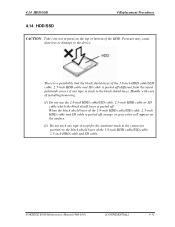
...R500 Maintenance Manual (960-634) [CONFIDENTIAL] 4-31 When the black shield layer of the 1.8-inch HDD cable/SSD cable, 2.5-inch HDD cable and SD cable is peeled off, orange or gray color will appear on the top or bottom of installing/removing. (1) Do not use the 1.8-inch HDD cable/SSD cable, 2.5-inch HDD...usual polyimide cover), if any tape (except for the insulator stuck to the connector portion) to the device. 4.14 HDD/SSD 4 Replacement Procedures 4.14 HDD/SSD 4 Replacement Procedures CAUTION: Take care not to press on the surface. (2) Do not stick any tape is stuck to the black...
...R500 Maintenance Manual (960-634) [CONFIDENTIAL] 4-31 When the black shield layer of the 1.8-inch HDD cable/SSD cable, 2.5-inch HDD cable and SD cable is peeled off, orange or gray color will appear on the top or bottom of installing/removing. (1) Do not use the 1.8-inch HDD cable/SSD cable, 2.5-inch HDD...usual polyimide cover), if any tape (except for the insulator stuck to the connector portion) to the device. 4.14 HDD/SSD 4 Replacement Procedures 4.14 HDD/SSD 4 Replacement Procedures CAUTION: Take care not to press on the surface. (2) Do not stick any tape is stuck to the black...
Maintenance Manual
Page 248
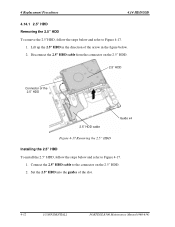
... of the 2.5" HDD 2.5" HDD cable Guide x4 Figure 4-17 Removing the 2.5" HDD Installing the 2.5" HDD To install the 2.5" HDD, follow the steps below and refer to the connector on the 2.5" HDD. 2.5" HDD Connector of the slot. 4-32 [CONFIDENTIAL] PORTÉGÉ R500 Maintenance Manual (960-634) 4 Replacement Procedures 4.14 HDD/SSD 4.14.1 2.5" HDD Removing the 2.5" HDD To remove the 2.5"HDD, follow the steps...
... of the 2.5" HDD 2.5" HDD cable Guide x4 Figure 4-17 Removing the 2.5" HDD Installing the 2.5" HDD To install the 2.5" HDD, follow the steps below and refer to the connector on the 2.5" HDD. 2.5" HDD Connector of the slot. 4-32 [CONFIDENTIAL] PORTÉGÉ R500 Maintenance Manual (960-634) 4 Replacement Procedures 4.14 HDD/SSD 4.14.1 2.5" HDD Removing the 2.5" HDD To remove the 2.5"HDD, follow the steps...

Maintenance Manual
Page 249
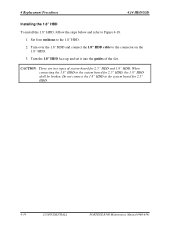
4.14 HDD/SSD 4 Replacement Procedures 4.14.2 1.8" HDD Removing the 1.8" HDD To remove the 1.8" HDD, follow the steps below and remove four cushions from the connector on the 1.8" HDD. Disconnect the 1.8" HDD cable from the 1.8" HDD. 2. Turn over the 1.8" HDD in the figure below and refer to Figure 4-18. 1. CAUTION: The 1.8-inch HDD cable and SSD cable are the same. 1.8" HDD Cushion x4 1.8" HDD cable Connector of the arrow in the direction of the 1.8" HDD Figure 4-18 Removing the 1.8" HDD Guide x4 PORTÉGÉ R500 Maintenance Manual (960-634) [CONFIDENTIAL] 4-33
4.14 HDD/SSD 4 Replacement Procedures 4.14.2 1.8" HDD Removing the 1.8" HDD To remove the 1.8" HDD, follow the steps below and remove four cushions from the connector on the 1.8" HDD. Disconnect the 1.8" HDD cable from the 1.8" HDD. 2. Turn over the 1.8" HDD in the figure below and refer to Figure 4-18. 1. CAUTION: The 1.8-inch HDD cable and SSD cable are the same. 1.8" HDD Cushion x4 1.8" HDD cable Connector of the arrow in the direction of the 1.8" HDD Figure 4-18 Removing the 1.8" HDD Guide x4 PORTÉGÉ R500 Maintenance Manual (960-634) [CONFIDENTIAL] 4-33
Maintenance Manual
Page 250
... to the connector on the 1.8" HDD. 3. Turn over the 1.8" HDD and connect the 1.8" HDD cable to the 1.8" HDD. 2. Turn the 1.8" HDD face up and set it into the guides of system board for 2.5" HDD. 4-34 [CONFIDENTIAL] PORTÉGÉ R500 Maintenance Manual (960-634) 4 Replacement Procedures 4.14 HDD/SSD Installing the 1.8" HDD To install the 1.8" HDD, follow the steps below and...
... to the connector on the 1.8" HDD. 3. Turn over the 1.8" HDD and connect the 1.8" HDD cable to the 1.8" HDD. 2. Turn the 1.8" HDD face up and set it into the guides of system board for 2.5" HDD. 4-34 [CONFIDENTIAL] PORTÉGÉ R500 Maintenance Manual (960-634) 4 Replacement Procedures 4.14 HDD/SSD Installing the 1.8" HDD To install the 1.8" HDD, follow the steps below and...
Maintenance Manual
Page 251
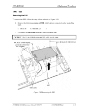
4.14 HDD/SSD 4 Replacement Procedures 4.14.3 SSD Removing the SSD To remove the SSD, follow the steps below and refer to Figure 4-19. 1. Remove the following screws and SSD. (SSD cable is connected on the SSD. M1.4x3C S-THIN HEAD Connector of the SSD) • M1.4×3C S-THIN HEAD ×3 2. CAUTION: The 1.8-inch HDD cable and SSD cable are the same. Disconnect the SSD cable from the connector on the back of the SSD (On the back) M1.4x3C S-THIN HEAD SSD cable SSD Figure 4-19 Removing the SSD PORTÉGÉ R500 Maintenance Manual (960-634) [CONFIDENTIAL] 4-35
4.14 HDD/SSD 4 Replacement Procedures 4.14.3 SSD Removing the SSD To remove the SSD, follow the steps below and refer to Figure 4-19. 1. Remove the following screws and SSD. (SSD cable is connected on the SSD. M1.4x3C S-THIN HEAD Connector of the SSD) • M1.4×3C S-THIN HEAD ×3 2. CAUTION: The 1.8-inch HDD cable and SSD cable are the same. Disconnect the SSD cable from the connector on the back of the SSD (On the back) M1.4x3C S-THIN HEAD SSD cable SSD Figure 4-19 Removing the SSD PORTÉGÉ R500 Maintenance Manual (960-634) [CONFIDENTIAL] 4-35
Maintenance Manual
Page 252
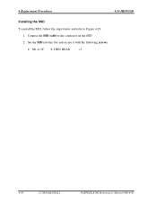
Connect the SSD cable to Figure 4-19. 1. Set the SSD into the slot and secure it with the following screws. • M1.4×3C S-THIN HEAD ×3 4-36 [CONFIDENTIAL] PORTÉGÉ R500 Maintenance Manual (960-634) 4 Replacement Procedures 4.14 HDD/SSD Installing the SSD To install the SSD, follow the steps below and refer to the connector on the SSD. 2.
Connect the SSD cable to Figure 4-19. 1. Set the SSD into the slot and secure it with the following screws. • M1.4×3C S-THIN HEAD ×3 4-36 [CONFIDENTIAL] PORTÉGÉ R500 Maintenance Manual (960-634) 4 Replacement Procedures 4.14 HDD/SSD Installing the SSD To install the SSD, follow the steps below and refer to the connector on the SSD. 2.
Maintenance Manual
Page 262
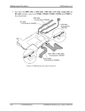
USB cable (Connected to CN9600) BT cable (Connected to CN4400) LAN cable (Connected to CN4100) HDD cable or SSD cable (Connected to CN1800) Sound cable (Connected to CN9500) Figure 4-28 Removing the system board (2) 4-46 [CONFIDENTIAL] PORTÉGÉ R500 Maintenance Manual (960-634) Disconnect the HDD cable (or SSD cable), USB cable, LAN cable, sound cable and BT cable from the connectors CN1800, CN9600, CN4100, CN9500 and CN4400 on the system board. 4 Replacement Procedures 4.18 System board 4.
USB cable (Connected to CN9600) BT cable (Connected to CN4400) LAN cable (Connected to CN4100) HDD cable or SSD cable (Connected to CN1800) Sound cable (Connected to CN9500) Figure 4-28 Removing the system board (2) 4-46 [CONFIDENTIAL] PORTÉGÉ R500 Maintenance Manual (960-634) Disconnect the HDD cable (or SSD cable), USB cable, LAN cable, sound cable and BT cable from the connectors CN1800, CN9600, CN4100, CN9500 and CN4400 on the system board. 4 Replacement Procedures 4.18 System board 4.
Maintenance Manual
Page 263
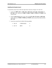
... ×1 • M3×5C BIND ×2 PORTÉGÉ R500 Maintenance Manual (960-634) [CONFIDENTIAL] 4-47 Connect the HDD cable (or SSD cable), USB cable, LAN cable, sound cable and BT cable to Figure 4-27 and 4-28. 1. 4.18 System board 4 Replacement Procedures Installing the System board To install the system board, follow...
... ×1 • M3×5C BIND ×2 PORTÉGÉ R500 Maintenance Manual (960-634) [CONFIDENTIAL] 4-47 Connect the HDD cable (or SSD cable), USB cable, LAN cable, sound cable and BT cable to Figure 4-27 and 4-28. 1. 4.18 System board 4 Replacement Procedures Installing the System board To install the system board, follow...
User Manual
Page 75
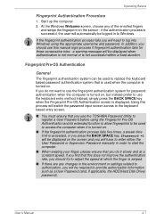
...in the environment or settings related to authorization, you will be used to replace the keyboard based password authentication system that is used to access the computer...changes in to provide authorization information such as a User Password (and, if applicable, the HDD(Hard Disk Drive) password). Fingerprint Pre-OS Authentication General The fingerprint authentication system can be required...password. a warning message will switch the password input screen across to use the TOSHIBA Password Utility to adjust the speed at a constant speed. Operating Basics Fingerprint ...
...in the environment or settings related to authorization, you will be used to replace the keyboard based password authentication system that is used to access the computer...changes in to provide authorization information such as a User Password (and, if applicable, the HDD(Hard Disk Drive) password). Fingerprint Pre-OS Authentication General The fingerprint authentication system can be required...password. a warning message will switch the password input screen across to use the TOSHIBA Password Utility to adjust the speed at a constant speed. Operating Basics Fingerprint ...
User Manual
Page 76
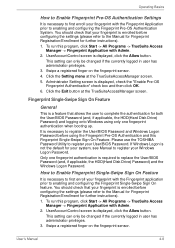
...has administrator privileges. 3. Fingerprint Single-Swipe Sign On Feature General This is a feature that allows the user to replace the User/BIOS Password (and, if applicable, the HDD(Hard Disk Drive) Password) and the Windows Logon Password. Swipe a registered finger on the fingerprint sensor. 4. User... configuring the Fingerprint Single-Swipe Sign On feature. Click the Exit button at the TrueSuiteAccessManager screen. 5. Please use the TOSHIBA Password Utility to register your User/BIOS Password. UserAccountControl screen is not the default for your system, see Manual to ...
...has administrator privileges. 3. Fingerprint Single-Swipe Sign On Feature General This is a feature that allows the user to replace the User/BIOS Password (and, if applicable, the HDD(Hard Disk Drive) Password) and the Windows Logon Password. Swipe a registered finger on the fingerprint sensor. 4. User... configuring the Fingerprint Single-Swipe Sign On feature. Click the Exit button at the TrueSuiteAccessManager screen. 5. Please use the TOSHIBA Password Utility to register your User/BIOS Password. UserAccountControl screen is not the default for your system, see Manual to ...
User Manual
Page 180
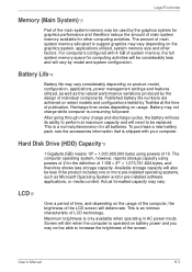
Published battery life numbers are achieved on select models and configurations tested by Toshiba at maximum capacity and will lose its ability to be considerably less and will dim when the computer is consuming full power. Available... utilized, system memory size and other computing activities. Battery may vary. Hard Disk Drive (HDD) Capacity*5 1 Gigabyte (GB) means 109 = 1,000,000,000 bytes using powers of main system memory available for computing activities will be replaced. User's Manual H-3 LCD*6 Over a period of time, and depending on the usage of...
Published battery life numbers are achieved on select models and configurations tested by Toshiba at maximum capacity and will lose its ability to be considerably less and will dim when the computer is consuming full power. Available... utilized, system memory size and other computing activities. Battery may vary. Hard Disk Drive (HDD) Capacity*5 1 Gigabyte (GB) means 109 = 1,000,000,000 bytes using powers of main system memory available for computing activities will be replaced. User's Manual H-3 LCD*6 Over a period of time, and depending on the usage of...

