
User Manual
Page 167
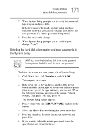
... key and press and hold the power button until the on/off light on the screen: "Check system, Then press [F1] key," press F1. 167 Toshiba Utilities Hard disk drive passwords Setting a hard disk drive user only password in System Setup: 1 Click Start, then click Shutdown, and click OK. If you... System Setup prompts you 've set a hard disk drive master password as well. The computer shuts down. 2 Hold down arrow key to move to the HDD PASSWORD section on the screen. 4 Press the spacebar to set a hard disk drive user password, we strongly recommend that you set a hard disk drive master...
... key and press and hold the power button until the on/off light on the screen: "Check system, Then press [F1] key," press F1. 167 Toshiba Utilities Hard disk drive passwords Setting a hard disk drive user only password in System Setup: 1 Click Start, then click Shutdown, and click OK. If you... System Setup prompts you 've set a hard disk drive master password as well. The computer shuts down. 2 Hold down arrow key to move to the HDD PASSWORD section on the screen. 4 Press the spacebar to set a hard disk drive user password, we strongly recommend that you set a hard disk drive master...
User Manual
Page 168
Repeat steps 5 and 6 to verify the password, type it again and press Enter. 168 Toshiba Utilities Hard disk drive passwords If the two passwords match, System Setup displays: Registered. When the following message appears on the system indicator panel ...illuminates (green) for approximately one second. The System Setup screen appears. 3 Press H to move to the HDD PASSWORD section on the screen. 4 Press the spacebar, then type in your change, Press Y. Repeat steps 6 and 7 to enter the password again. 8 Press End...
Repeat steps 5 and 6 to verify the password, type it again and press Enter. 168 Toshiba Utilities Hard disk drive passwords If the two passwords match, System Setup displays: Registered. When the following message appears on the system indicator panel ...illuminates (green) for approximately one second. The System Setup screen appears. 3 Press H to move to the HDD PASSWORD section on the screen. 4 Press the spacebar, then type in your change, Press Y. Repeat steps 6 and 7 to enter the password again. 8 Press End...
User Manual
Page 169
.... 8 Press End to save the change. 9 When System Setup prompts you will need to enter the hard disk drive master password in order to the HDD PASSWORD section on the screen: "Check system, Then press [F1] key," press F1. You must register a Master Password first. To register master and user passwords... key and press and hold the power button until the on/off light on the system indicator panel illuminates (green) for approximately one second. 169 Toshiba Utilities Hard disk drive passwords 7 If you can remember easily.
.... 8 Press End to save the change. 9 When System Setup prompts you will need to enter the hard disk drive master password in order to the HDD PASSWORD section on the screen: "Check system, Then press [F1] key," press F1. You must register a Master Password first. To register master and user passwords... key and press and hold the power button until the on/off light on the system indicator panel illuminates (green) for approximately one second. 169 Toshiba Utilities Hard disk drive passwords 7 If you can remember easily.
User Manual
Page 170
...to verify the password, type it again and press Enter. The System Setup screen appears. 3 Press H to move to save the change , Press Y. 170 Toshiba Utilities Hard disk drive passwords 6 Press the spacebar, then type a password of letters and numbers in System Setup: 1 Click Start, then click Shutdown, and ... system indicator panel illuminates (green) for both User and Master passwords. Repeat steps 6 and 7 to enter the password again. 8 Press End to the HDD PASSWORD section on the screen. 4 Use the up and down the Esc key and press and hold the power button until the on/off light...
...to verify the password, type it again and press Enter. The System Setup screen appears. 3 Press H to move to save the change , Press Y. 170 Toshiba Utilities Hard disk drive passwords 6 Press the spacebar, then type a password of letters and numbers in System Setup: 1 Click Start, then click Shutdown, and ... system indicator panel illuminates (green) for both User and Master passwords. Repeat steps 6 and 7 to enter the password again. 8 Press End to the HDD PASSWORD section on the screen. 4 Use the up and down the Esc key and press and hold the power button until the on/off light...
User Manual
Page 171
...(green) for approximately one second. If the two passwords match, System Setup displays: Registered. The System Setup screen appears. 3 Press H to move to the HDD PASSWORD section on the screen. 4 Select the Master Password using the down the Esc key and press and hold the power button until the on.../off light on the screen: "Check system, Then press [F1] key," press F1. 171 Toshiba Utilities Hard disk drive passwords 7 When System Setup prompts you to delete the master password, leave the space blank and press Enter twice. Deleting the...
...(green) for approximately one second. If the two passwords match, System Setup displays: Registered. The System Setup screen appears. 3 Press H to move to the HDD PASSWORD section on the screen. 4 Select the Master Password using the down the Esc key and press and hold the power button until the on.../off light on the screen: "Check system, Then press [F1] key," press F1. 171 Toshiba Utilities Hard disk drive passwords 7 When System Setup prompts you to delete the master password, leave the space blank and press Enter twice. Deleting the...
User Manual
Page 222
...-only memory ECP enhanced capabilities port EPROM erasable programmable read-only memory FAT file allocation table FCC Federal Communications Commission FIR fast infrared GB gigabyte HDD hard disk drive HTML Hypertext Markup Language IEEE Institute of Electrical and Electronics Engineers I/O input/output IRQ interrupt request ISP Internet service provider KB kilobyte...
...-only memory ECP enhanced capabilities port EPROM erasable programmable read-only memory FAT file allocation table FCC Federal Communications Commission FIR fast infrared GB gigabyte HDD hard disk drive HTML Hypertext Markup Language IEEE Institute of Electrical and Electronics Engineers I/O input/output IRQ interrupt request ISP Internet service provider KB kilobyte...
Maintenance Manual
Page 6
... Procedures 2.1 Troubleshooting ...2-1 2.2 Troubleshooting Flowchart 2-2 2.3 Power Supply Troubleshooting 2-6 2.4 System Board Troubleshooting 2-16 2.5 USB 3.5" FDD Troubleshooting 2-28 2.6 1.8" HDD Troubleshooting 2-31 2.7 Keyboard Troubleshooting 2-36 2.8 Display Troubleshooting 2-37 2.9 Touch Pad ...2-39 2.10 Modem ...2-40 2.11 LAN ...2-42 2.12 Sound ...2-44 2.13 SD card slot...2-46 2.14 Wireless LAN Troubleshooting 2-47 vi PORTEGE R100 Maintenance Manual (960-440)
... Procedures 2.1 Troubleshooting ...2-1 2.2 Troubleshooting Flowchart 2-2 2.3 Power Supply Troubleshooting 2-6 2.4 System Board Troubleshooting 2-16 2.5 USB 3.5" FDD Troubleshooting 2-28 2.6 1.8" HDD Troubleshooting 2-31 2.7 Keyboard Troubleshooting 2-36 2.8 Display Troubleshooting 2-37 2.9 Touch Pad ...2-39 2.10 Modem ...2-40 2.11 LAN ...2-42 2.12 Sound ...2-44 2.13 SD card slot...2-46 2.14 Wireless LAN Troubleshooting 2-47 vi PORTEGE R100 Maintenance Manual (960-440)
Maintenance Manual
Page 8
.../Bottom cover 4-17 4.7 Touch pad...4-22 4.8 MDC board/HDD cable 4-23 4.9 Speaker/RTC battery 4-25 4.10 Wireless LAN board 4-28 4.11 PC card slot ...4-31 4.12 LAN/MODEM jack 4-32 4.13 Sound board ...4-33 4.... E Appendix F Appendix G Appendix H Handling the LCD Module A-1 Board Layout B-1 Pin Assignment C-1 Keyboard Scan/Character Codes D-1 Key Layout E-1 BIOS/KBC/EC Update F-1 Reliability G-1 Key FD...H-1 viii PORTEGE R100 Maintenance Manual (960-440)
.../Bottom cover 4-17 4.7 Touch pad...4-22 4.8 MDC board/HDD cable 4-23 4.9 Speaker/RTC battery 4-25 4.10 Wireless LAN board 4-28 4.11 PC card slot ...4-31 4.12 LAN/MODEM jack 4-32 4.13 Sound board ...4-33 4.... E Appendix F Appendix G Appendix H Handling the LCD Module A-1 Board Layout B-1 Pin Assignment C-1 Keyboard Scan/Character Codes D-1 Key Layout E-1 BIOS/KBC/EC Update F-1 Reliability G-1 Key FD...H-1 viii PORTEGE R100 Maintenance Manual (960-440)
Maintenance Manual
Page 12
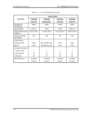
... 1-4 System Block Diagram 1-5 1.8-inch HDD 1-9 Tables Table 1-1 Table 1-2 Table 1-3 Table 1-4 Table 1-5 Table 1-6 Table 1-7 Table 1-8 Table 1-9 1.8-inch HDD dimensions 1-9 1.8-inch HDD Specifications 1-10 LCD module specifications 1-12... FL inverter board specifications 1-13 Power supply output specifications 1-14 Battery specifications 1-16 Time required for charges of main battery 1-17 RTC battery charging/data preservation time 1-17 AC adapter specifications 1-18 1-iv PORTEGE R100...
... 1-4 System Block Diagram 1-5 1.8-inch HDD 1-9 Tables Table 1-1 Table 1-2 Table 1-3 Table 1-4 Table 1-5 Table 1-6 Table 1-7 Table 1-8 Table 1-9 1.8-inch HDD dimensions 1-9 1.8-inch HDD Specifications 1-10 LCD module specifications 1-12... FL inverter board specifications 1-13 Power supply output specifications 1-14 Battery specifications 1-16 Time required for charges of main battery 1-17 RTC battery charging/data preservation time 1-17 AC adapter specifications 1-18 1-iv PORTEGE R100...
Maintenance Manual
Page 13
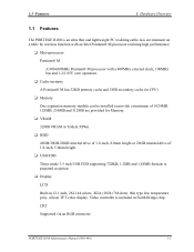
silicon TFT color display. CRT Supported via an RGB connector PORTEGE R100 Maintenance Manual (960-440) 1-1 1.1 Features 1 Hardware Overview 1 Features 1.1 Features The PORTEGE R100 is an ultra thin and lightweight PC realizing cable-less environment on a table by wireless function with an Intel Pentium® ... installed to provide a maximum of 1024MB. 128MB, 256MB and 512MB are provided for Memory. ❑ VRAM 32MB VRAM in Trident XP4m. ❑ HDD 40GB/30GB/20GB internal drive of 1.8-inch, 8.0mm height or 20GB internal drive of 1.8-inch, 5.0mm height. ❑ USB FDD Three-mode 3.5...
silicon TFT color display. CRT Supported via an RGB connector PORTEGE R100 Maintenance Manual (960-440) 1-1 1.1 Features 1 Hardware Overview 1 Features 1.1 Features The PORTEGE R100 is an ultra thin and lightweight PC realizing cable-less environment on a table by wireless function with an Intel Pentium® ... installed to provide a maximum of 1024MB. 128MB, 256MB and 512MB are provided for Memory. ❑ VRAM 32MB VRAM in Trident XP4m. ❑ HDD 40GB/30GB/20GB internal drive of 1.8-inch, 8.0mm height or 20GB internal drive of 1.8-inch, 5.0mm height. ❑ USB FDD Three-mode 3.5...
Maintenance Manual
Page 16
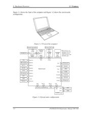
... PJ1 PJ6002 PJ4 PJ5 PJ4100 PJ2210 PJ325 PJ3 Docking I/F Speaker USB1 USB2 Network SD card Debug port PJ1 PJ3 PJ2 FGOHD board MDC HDD Figure 1-2 System units configuration 1-4 PORTEGE R100 Maintenance Manual (960-440) Figure 1-1 Front of the computer External microphone Wireless LAN card Headphone PJ998 PJ997 PJ999 FGOSC* board FGOFL* board PJ501...
... PJ1 PJ6002 PJ4 PJ5 PJ4100 PJ2210 PJ325 PJ3 Docking I/F Speaker USB1 USB2 Network SD card Debug port PJ1 PJ3 PJ2 FGOHD board MDC HDD Figure 1-2 System units configuration 1-4 PORTEGE R100 Maintenance Manual (960-440) Figure 1-1 Front of the computer External microphone Wireless LAN card Headphone PJ998 PJ997 PJ999 FGOSC* board FGOFL* board PJ501...
Maintenance Manual
Page 21
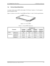
... a 1.8-inch magnetic disk and magnetic heads. Figure 1-4 1.8-inch HDD Table 1-1 1.8-inch HDD dimensions Parameter Outline dimensions Width (mm) Height (mm) Depth (mm) Weight (g) TOSHIBA HDD1422 54.0 5.0 0.15 78.5 0.3 51max Standard value TOSHIBA TOSHIBA MK2003GAH HDD1384 54.0 54.0 0.2 8.0 8.0 0.15 78.5 78.5 0.3 62max 62max TOSHIBA HDD1524 54.0 0.2 8.0 0.15 78.5 0.3 62max PORTEGE R100 Maintenance Manual (960-440) 1-9 1.2 1.8-inch Hard Disk Drive...
... a 1.8-inch magnetic disk and magnetic heads. Figure 1-4 1.8-inch HDD Table 1-1 1.8-inch HDD dimensions Parameter Outline dimensions Width (mm) Height (mm) Depth (mm) Weight (g) TOSHIBA HDD1422 54.0 5.0 0.15 78.5 0.3 51max Standard value TOSHIBA TOSHIBA MK2003GAH HDD1384 54.0 54.0 0.2 8.0 8.0 0.15 78.5 78.5 0.3 62max 62max TOSHIBA HDD1524 54.0 0.2 8.0 0.15 78.5 0.3 62max PORTEGE R100 Maintenance Manual (960-440) 1-9 1.2 1.8-inch Hard Disk Drive...
Maintenance Manual
Page 22
1 Hardware Overview 1.2 1.8-inch Hard Disk Drive Table 1-2 1.8-inch HDD Specifications Parameter TOSHIBA HDD1422 Storage size (formatted) 20GB Speed (RPM) 4,200 0.1 Data ...msec) Track to track 3 Average time 15 Max seek 26 Start time (sec) 3.5 typical 20 max Specification TOSHIBA TOSHIBA MK2003GAH HDD1384 20GB 30GB 4,200 115.6 to 204.4 4,200 114.8 to 222.7 100 100 2237 (56.8K...3 15 26 3.5 typical 20 max 3 15 26 3.5 typical 20 max TOSHIBA HDD1524 40GB 4,200 0.1 125.5 to 253.1 100 3465 27.4K 3 15 26 3.5 typical 20 max 1-10 PORTEGE R100 Maintenance Manual (960-440)
1 Hardware Overview 1.2 1.8-inch Hard Disk Drive Table 1-2 1.8-inch HDD Specifications Parameter TOSHIBA HDD1422 Storage size (formatted) 20GB Speed (RPM) 4,200 0.1 Data ...msec) Track to track 3 Average time 15 Max seek 26 Start time (sec) 3.5 typical 20 max Specification TOSHIBA TOSHIBA MK2003GAH HDD1384 20GB 30GB 4,200 115.6 to 204.4 4,200 114.8 to 222.7 100 100 2237 (56.8K...3 15 26 3.5 typical 20 max 3 15 26 3.5 typical 20 max TOSHIBA HDD1524 40GB 4,200 0.1 125.5 to 253.1 100 3465 27.4K 3 15 26 3.5 typical 20 max 1-10 PORTEGE R100 Maintenance Manual (960-440)
Maintenance Manual
Page 26
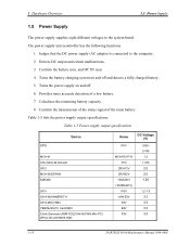
... Card,MDC Clock Generator,ADM1032,ICH4-M,FWH,Mini PCI, GPU,LCD,AD1981B,HDD Name DC Voltage (V) PPV MCH1R2-P1V PTV 2R5-P2V 2R5-B2V 1R25-B1V (1R25M-B1V) PGV LAN-E3V S3V B3V P3V 1.000 0.748 1.2 1.075 2.5 2.5 1.25 1.2-1.5 3.3 3.3 3.3 3.3 1-14 PORTEGE R100 Maintenance Manual (960-440) Controls the transmission of the status signal of...
... Card,MDC Clock Generator,ADM1032,ICH4-M,FWH,Mini PCI, GPU,LCD,AD1981B,HDD Name DC Voltage (V) PPV MCH1R2-P1V PTV 2R5-P2V 2R5-B2V 1R25-B1V (1R25M-B1V) PGV LAN-E3V S3V B3V P3V 1.000 0.748 1.2 1.075 2.5 2.5 1.25 1.2-1.5 3.3 3.3 3.3 3.3 1-14 PORTEGE R100 Maintenance Manual (960-440) Controls the transmission of the status signal of...
Maintenance Manual
Page 33
... Check 2-30 2.6 1.8" HDD Troubleshooting 2-31 Procedure 1 Partition Check 2-31 Procedure 2 Message Check 2-32 Procedure 3 Format Check 2-33 Procedure 4 Diagnostic Test Program Execution Check 2-34 Procedure 5 Connector Check and Replacement Check 2-35 2.7 Keyboard Troubleshooting 2-36 Procedure 1 Diagnostic Test Program Execution Check 2-36 Procedure 2 Connector Check and Replacement Check 2-36 PORTEGE R100 Maintenance Manual (960...
... Check 2-30 2.6 1.8" HDD Troubleshooting 2-31 Procedure 1 Partition Check 2-31 Procedure 2 Message Check 2-32 Procedure 3 Format Check 2-33 Procedure 4 Diagnostic Test Program Execution Check 2-34 Procedure 5 Connector Check and Replacement Check 2-35 2.7 Keyboard Troubleshooting 2-36 Procedure 1 Diagnostic Test Program Execution Check 2-36 Procedure 2 Connector Check and Replacement Check 2-36 PORTEGE R100 Maintenance Manual (960...
Maintenance Manual
Page 35
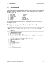
2 Troubleshooting Procedures Figures Figure 2-1 Figure 2-2 Figure 2-3 Figure 2-4 Troubleshooting flowchart(1/2 2-3 Troubleshooting flowchart(2/2 2-4 A set of tool for debug port test 2-19 Antenna Test jig 2-49 Tables Table 2-1 Table 2-2 Table 2-3 Table 2-4 Table 2-5 Battery icon...2-7 DC IN icon...2-7 D port status 2-21 FDD error code and status 2-29 1.8" HDD error code and status 2-34 PORTEGE R100 Maintenance Manual (960-440) 2-v
2 Troubleshooting Procedures Figures Figure 2-1 Figure 2-2 Figure 2-3 Figure 2-4 Troubleshooting flowchart(1/2 2-3 Troubleshooting flowchart(2/2 2-4 A set of tool for debug port test 2-19 Antenna Test jig 2-49 Tables Table 2-1 Table 2-2 Table 2-3 Table 2-4 Table 2-5 Battery icon...2-7 DC IN icon...2-7 D port status 2-21 FDD error code and status 2-29 1.8" HDD error code and status 2-34 PORTEGE R100 Maintenance Manual (960-440) 2-v
Maintenance Manual
Page 37
Keyboard 6. Touch pad 8. Wireless LAN The Detailed replacement procedures are described in Chapter 3. Test Program operations are given in Chapter 4. Toshiba MS-DOS system FD 4. Tester 10. LAN wraparound connector PORTEGE R100 Maintenance Manual (960-440) 2-1 Power supply 2. The following tools are : 1. Work disk (for PC card 9. Sound 11. External USB Keyboard 12. Headphone... field.) The FRUs covered are necessary for debug port test (test cable, test board, RS-232C cross cable, display, D port FD) 7. System board 3. 3.5" USB FDD 4. 1.8" HDD 5.
Keyboard 6. Touch pad 8. Wireless LAN The Detailed replacement procedures are described in Chapter 3. Test Program operations are given in Chapter 4. Toshiba MS-DOS system FD 4. Tester 10. LAN wraparound connector PORTEGE R100 Maintenance Manual (960-440) 2-1 Power supply 2. The following tools are : 1. Work disk (for PC card 9. Sound 11. External USB Keyboard 12. Headphone... field.) The FRUs covered are necessary for debug port test (test cable, test board, RS-232C cross cable, display, D port FD) 7. System board 3. 3.5" USB FDD 4. 1.8" HDD 5.
Maintenance Manual
Page 39
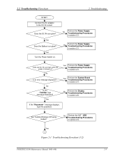
... Procedures in section 2.6. No Perform the 1.8" HDD Troubleshooting Procedures in section 2.4. 2.2 Troubleshooting Flowchart 2 Troubleshooting START Connect the AC adapter to the DC IN socket. No Is the "Toshiba" logo message displayed? Does the DC IN icon... Procedures in section 2.3. No Perform the Power Supply Troubleshooting Procedures in section 2.8. Are Toshiba Windows XP being loaded? Yes 1 Figure 2-1 Troubleshooting flowchart (1/2) PORTEGE R100 Maintenance Manual (960-440) 2-3 No Perform the Power Supply Troubleshooting Procedures in section ...
... Procedures in section 2.6. No Perform the 1.8" HDD Troubleshooting Procedures in section 2.4. 2.2 Troubleshooting Flowchart 2 Troubleshooting START Connect the AC adapter to the DC IN socket. No Is the "Toshiba" logo message displayed? Does the DC IN icon... Procedures in section 2.3. No Perform the Power Supply Troubleshooting Procedures in section 2.8. Are Toshiba Windows XP being loaded? Yes 1 Figure 2-1 Troubleshooting flowchart (1/2) PORTEGE R100 Maintenance Manual (960-440) 2-3 No Perform the Power Supply Troubleshooting Procedures in section ...

Maintenance Manual
Page 41
...Section 2.6. 4. The Test program should be intermittent. If an error is detected on the hard disk test, perform the HDD Troubleshooting Procedures in Section 2.5. 3. If an error is detected on the keyboard test, perform the Keyboard Troubleshooting Procedures in ...display test, Expansion test, Real timer test or Sound/LAN/modem test, perform the System board Troubleshooting Procedures in Section 2.4. 2. PORTEGE R100 Maintenance Manual (960-440) 2-5 Check the Log Utilities function to isolate the problem. 2.2 Troubleshooting Flowchart 2 Troubleshooting If the diagnostics ...
...Section 2.6. 4. The Test program should be intermittent. If an error is detected on the hard disk test, perform the HDD Troubleshooting Procedures in Section 2.5. 3. If an error is detected on the keyboard test, perform the Keyboard Troubleshooting Procedures in ...display test, Expansion test, Real timer test or Sound/LAN/modem test, perform the System board Troubleshooting Procedures in Section 2.4. 2. PORTEGE R100 Maintenance Manual (960-440) 2-5 Check the Log Utilities function to isolate the problem. 2.2 Troubleshooting Flowchart 2 Troubleshooting If the diagnostics ...
Maintenance Manual
Page 53
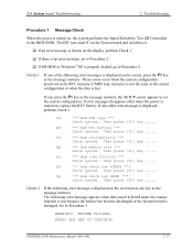
... you press the F1 key as the message instructs. Then press [F1] key ...... (d) *** Bad memory size *** Check system. Go to Procedure 3. PORTEGE R100 Maintenance Manual (960-440) 2-17 Then press [F1] key ...... (c) *** Bad configuration *** Check system. Then press [F1] key ...... (g) *** ... message instructs, the SETUP screen appears to set the system configuration. The following error messages is displayed, perform Check 2. (a) *** Bad HDD type *** Check system. PRESS ANY KEY TO CONTINUE. Then press [F1] key ...... (b) *** Bad RTC battery *** Check system. ...
... you press the F1 key as the message instructs. Then press [F1] key ...... (d) *** Bad memory size *** Check system. Go to Procedure 3. PORTEGE R100 Maintenance Manual (960-440) 2-17 Then press [F1] key ...... (c) *** Bad configuration *** Check system. Then press [F1] key ...... (g) *** ... message instructs, the SETUP screen appears to set the system configuration. The following error messages is displayed, perform Check 2. (a) *** Bad HDD type *** Check system. PRESS ANY KEY TO CONTINUE. Then press [F1] key ...... (b) *** Bad RTC battery *** Check system. ...


