Toshiba User's Guide for Portege A600
Page 59
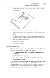
... module is displayed below the System heading under Memory (RAM). For more information on inserting the main battery, see "Inserting a charged battery" on page 53), and then check that the computer has recognized the change. Getting Started Adding memory (optional) 59 3 Gently lift the memory module to a 30-degree angle and slide it out of the slot. (Sample Illustration) Removing the memory module 4 Replace the memory module slot cover and secure it using...
... module is displayed below the System heading under Memory (RAM). For more information on inserting the main battery, see "Inserting a charged battery" on page 53), and then check that the computer has recognized the change. Getting Started Adding memory (optional) 59 3 Gently lift the memory module to a 30-degree angle and slide it out of the slot. (Sample Illustration) Removing the memory module 4 Replace the memory module slot cover and secure it using...
Toshiba User's Guide for Portege A600
Page 175
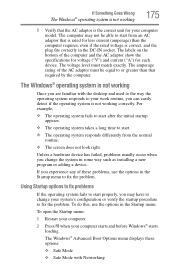
... with Networking Using Startup options to fix problems If the operating system fails to fix the problem. The Windows® Advanced Boot Options menu displays these problems, use the options in some way such as installing a new program or adding a device. The voltage level must be able to or greater than the computer requires, even if the rated voltage is correct, and the plug fits correctly in the Startup menu to start from...
... with Networking Using Startup options to fix problems If the operating system fails to fix the problem. The Windows® Advanced Boot Options menu displays these problems, use the options in some way such as installing a new program or adding a device. The voltage level must be able to or greater than the computer requires, even if the rated voltage is correct, and the plug fits correctly in the Startup menu to start from...
Toshiba User's Guide for Portege A600
Page 179
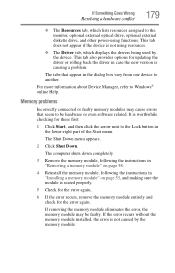
... driver in the dialog box vary from one device to be faulty. The tabs that seem to another. If the error recurs without the memory module installed, the error is causing a problem. Memory problems Incorrectly connected or faulty memory modules may be hardware or even software related. The Shut Down menu appears. 2 Click Shut Down. For more information about Device Manager, refer to the monitor, optional external optical drive, optional external diskette drive, and other power-using functions...
... driver in the dialog box vary from one device to be faulty. The tabs that seem to another. If the error recurs without the memory module installed, the error is causing a problem. Memory problems Incorrectly connected or faulty memory modules may be hardware or even software related. The Shut Down menu appears. 2 Click Shut Down. For more information about Device Manager, refer to the monitor, optional external optical drive, optional external diskette drive, and other power-using functions...

Toshiba User's Guide for Portege A600
Page 231
... using a pointing device such as the battery save mode. (2) A key or combination of keys that saves to the internal storage drive the current state of refreshing a computer screen, in combination with any other services. When you turn the computer off . high-density diskette - A method of your work , including all open files and programs, when you use to interact with the Fn key can set system options or control...
... using a pointing device such as the battery save mode. (2) A key or combination of keys that saves to the internal storage drive the current state of refreshing a computer screen, in combination with any other services. When you turn the computer off . high-density diskette - A method of your work , including all open files and programs, when you use to interact with the Fn key can set system options or control...
Toshiba User's Guide for Portege A600
Page 239
... function keys 91 H hardware conflicts 177 resolving 178 headphones using 130 Help and Support Windows® operating system 177 Hibernation mode 76 configuring 80 hot key 210 starting again from 82 hot key disabling or enabling TouchPad™ 214 disabling or enabling wireless devices 213 display brightness 212 Hibernation mode 210 keyboard overlays 216 Lock (Instant security) 207 Output (Display switch) 211 power plan 208 Sleep mode 209 volume mute 206 Zoom (Display resolution) 215 zooming in 216 zooming out 216 Hot Key Cards 201 Hot key functions 205 hot key power...
... function keys 91 H hardware conflicts 177 resolving 178 headphones using 130 Help and Support Windows® operating system 177 Hibernation mode 76 configuring 80 hot key 210 starting again from 82 hot key disabling or enabling TouchPad™ 214 disabling or enabling wireless devices 213 display brightness 212 Hibernation mode 210 keyboard overlays 216 Lock (Instant security) 207 Output (Display switch) 211 power plan 208 Sleep mode 209 volume mute 206 Zoom (Display resolution) 215 zooming in 216 zooming out 216 Hot Key Cards 201 Hot key functions 205 hot key power...
Toshiba User's Guide for Portege A600
Page 240
...troubleshooting 181 unexpected characters 181 using 90 keyboard, external 73 keyboard, full-size 90 L light AC power 47 drive in-use indicator 99 lock computer, using 86 M main battery changing 116 installing 116, 118 removing 116 safety precautions 119 manual eject hole optical drive 100 memory adding 53 problem solving 179 removing memory module slot cover 55 memory module installation 53 installing inserting into socket 55 removing 58, 59 memory module slot 55 microphone using 130 monitor connecting 71 monitor problems monitor not working 182 mouse installing 73 mouse utility 154 N network...
...troubleshooting 181 unexpected characters 181 using 90 keyboard, external 73 keyboard, full-size 90 L light AC power 47 drive in-use indicator 99 lock computer, using 86 M main battery changing 116 installing 116, 118 removing 116 safety precautions 119 manual eject hole optical drive 100 memory adding 53 problem solving 179 removing memory module slot cover 55 memory module installation 53 installing inserting into socket 55 removing 58, 59 memory module slot 55 microphone using 130 monitor connecting 71 monitor problems monitor not working 182 mouse installing 73 mouse utility 154 N network...
Toshiba User's Guide for Portege A600
Page 241
... overlay keys 91 P password deleting a supervisor 146 disabling a user 147 setting a user 146 supervisor set up 145 types 144 passwords instant, using 144 setting 144 port monitor 71 power computer will not start 172 connecting cable to AC adaptor 48 cord/cable 49 cord/cable connectors 217 energy-saving features 105 problem solving 180 turning on 52 power button 52, 61 power plan hot key 115 power plans 114 power source connecting 48 powering down using Hibernation 80 using Shut Down 78 using Sleep...
... overlay keys 91 P password deleting a supervisor 146 disabling a user 147 setting a user 146 supervisor set up 145 types 144 passwords instant, using 144 setting 144 port monitor 71 power computer will not start 172 connecting cable to AC adaptor 48 cord/cable 49 cord/cable connectors 217 energy-saving features 105 problem solving 180 turning on 52 power button 52, 61 power plan hot key 115 power plans 114 power source connecting 48 powering down using Hibernation 80 using Shut Down 78 using Sleep...
User Manual
Page 3
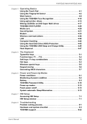
... Charge Utility 4-45 Heat dispersal 4-47 Chapter 5 The Keyboard Typewriter keys 5-1 Function keys: F1 ... PORTÉGÉ R600/PORTÉGÉ A600 Chapter 4 Operating Basics Using the Touch Pad 4-1 Using the Fingerprint Sensor 4-2 Web Camera 4-9 Using the TOSHIBA Face Recognition 4-10 Using optical disc drives 4-13 Writing CD/DVDs on /off 6-13 System automatic Sleep/Hibernation 6-13 Chapter 7 HW Setup Accessing HW Setup 7-1 HW Setup window 7-1 Chapter 8 Troubleshooting Problem solving process 8-1 Hardware and system checklist 8-3 TOSHIBA support 8-22 User's Manual...
... Charge Utility 4-45 Heat dispersal 4-47 Chapter 5 The Keyboard Typewriter keys 5-1 Function keys: F1 ... PORTÉGÉ R600/PORTÉGÉ A600 Chapter 4 Operating Basics Using the Touch Pad 4-1 Using the Fingerprint Sensor 4-2 Web Camera 4-9 Using the TOSHIBA Face Recognition 4-10 Using optical disc drives 4-13 Writing CD/DVDs on /off 6-13 System automatic Sleep/Hibernation 6-13 Chapter 7 HW Setup Accessing HW Setup 7-1 HW Setup window 7-1 Chapter 8 Troubleshooting Problem solving process 8-1 Hardware and system checklist 8-3 TOSHIBA support 8-22 User's Manual...

User Manual
Page 30
... the Recovery Disc Creator icon on the Windows Vista® desktop, or select the application from Start Menu. Getting Started Restoring the pre-installed Software Depending on the model you purchased, different ways for it to load the Windows Vista® operating system from the hard disk drive as screen savers which the recovery image can put a heavy load on the CPU. ■ Operate the computer at full power. ■ Do not use utilities...
... the Recovery Disc Creator icon on the Windows Vista® desktop, or select the application from Start Menu. Getting Started Restoring the pre-installed Software Depending on the model you purchased, different ways for it to load the Windows Vista® operating system from the hard disk drive as screen savers which the recovery image can put a heavy load on the CPU. ■ Operate the computer at full power. ■ Do not use utilities...

User Manual
Page 65
... Card, microSD Card) ■ Additional memory module Peripheral devices ■ USB FDD Kit ■ External monitor ■ eSATA ■ TOSHIBA Slim Port Replicator II User's Manual 3-14 Press the PGDN key. 4. Press the Y key to accept the changes. This section describes the connection or installation of the connector before connecting. Turn on how to set to Yes, switch the Hide TPM setting from Yes to use this utility, please refer to the Infineon TPM Installation Guide. BIOS setup...
... Card, microSD Card) ■ Additional memory module Peripheral devices ■ USB FDD Kit ■ External monitor ■ eSATA ■ TOSHIBA Slim Port Replicator II User's Manual 3-14 Press the PGDN key. 4. Press the Y key to accept the changes. This section describes the connection or installation of the connector before connecting. Turn on how to set to Yes, switch the Hide TPM setting from Yes to use this utility, please refer to the Infineon TPM Installation Guide. BIOS setup...
User Manual
Page 80
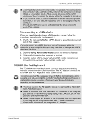
... interface on . ■ If you can not use the following computer's ports: LAN jack, DC IN 15V jack and External monitor port. ■ When connecting an AC Adaptor to make sure all activity has stopped. Logging onto a LAN using an eSATA device, you connect an eSATA device after the computer has already been turned on the Windows Taskbar. 3. Hardware, Utilities and Options ■ A connected eSATA device may lose data or damage an eSATA...
... interface on . ■ If you can not use the following computer's ports: LAN jack, DC IN 15V jack and External monitor port. ■ When connecting an AC Adaptor to make sure all activity has stopped. Logging onto a LAN using an eSATA device, you connect an eSATA device after the computer has already been turned on the Windows Taskbar. 3. Hardware, Utilities and Options ■ A connected eSATA device may lose data or damage an eSATA...

User Manual
Page 141
... instructions. ■ Make sure the battery is securely installed in Sleep Mode. The battery can explode if not replaced, used , handled or disposed. Power and Power-Up Modes Real Time Clock (RTC) battery The Real Time Clock (RTC) battery provides power for the internal real time clock and calendar function and also maintains the system configuration while the computer is turned off the power and disconnecting the AC adaptor. in order...
... instructions. ■ Make sure the battery is securely installed in Sleep Mode. The battery can explode if not replaced, used , handled or disposed. Power and Power-Up Modes Real Time Clock (RTC) battery The Real Time Clock (RTC) battery provides power for the internal real time clock and calendar function and also maintains the system configuration while the computer is turned off the power and disconnecting the AC adaptor. in order...

User Manual
Page 163
... each key). the BIOS setup application will end and the computer will load. Press the END key - Password Problem Procedure Cannot enter password Please refer to use the keyboard, you will be caused by using the RTC battery is low or CMOS checksum is not activated - please refer to set the date and screen: time in any way (remapping involves changing or reassigning the function of the computer - User's Manual 8-7 Troubleshooting...
... each key). the BIOS setup application will end and the computer will load. Press the END key - Password Problem Procedure Cannot enter password Please refer to use the keyboard, you will be caused by using the RTC battery is low or CMOS checksum is not activated - please refer to set the date and screen: time in any way (remapping involves changing or reassigning the function of the computer - User's Manual 8-7 Troubleshooting...
User Manual
Page 197
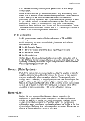
... device drivers and/or applications may not be compatible with a 64-bit CPU and therefore may be used outside recommended conditions. Contact Toshiba technical service and support, refer to TOSHIBA support section in your computer product may also vary from specifications due to the product when used by periodically storing it on the graphics system, applications utilized, system memory size and other computing activities. Battery...
... device drivers and/or applications may not be compatible with a 64-bit CPU and therefore may be used outside recommended conditions. Contact Toshiba technical service and support, refer to TOSHIBA support section in your computer product may also vary from specifications due to the product when used by periodically storing it on the graphics system, applications utilized, system memory size and other computing activities. Battery...

User Manual
Page 210
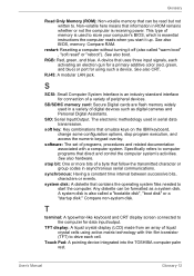
... used as ROM. keyboard: An input device containing switches that transmits a specific code to the computer's main memory, where programs are activated by a communications link that displays a list of the glass. Each keystroke activates a switch that are run and data is applied. See also byte and megabyte. L L1 cache: Level one of the main parts of the liquid crystal. It is RAM. Light Emitting Diode (LED): A semiconductor device...
... used as ROM. keyboard: An input device containing switches that transmits a specific code to the computer's main memory, where programs are activated by a communications link that displays a list of the glass. Each keystroke activates a switch that are run and data is applied. See also byte and megabyte. L L1 cache: Level one of the main parts of the liquid crystal. It is RAM. Light Emitting Diode (LED): A semiconductor device...
User Manual
Page 213
... control the computer system's activities. soft key: Key combinations that uses three input signals, each cell. Touch Pad: A pointing device integrated into the TOSHIBA computer palm rest. A device that emulate keys on the IBM keyboard, change some configuration options, stop bit: One or more bits of liquid crystal cells using active-matrix technology with a computer system. stop program execution, and access the numeric keypad overlay. TFT display: A liquid crystal display (LCD...
... control the computer system's activities. soft key: Key combinations that uses three input signals, each cell. Touch Pad: A pointing device integrated into the TOSHIBA computer palm rest. A device that emulate keys on the IBM keyboard, change some configuration options, stop bit: One or more bits of liquid crystal cells using active-matrix technology with a computer system. stop program execution, and access the numeric keypad overlay. TFT display: A liquid crystal display (LCD...
Maintenance Manual
Page 3
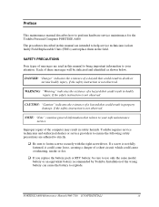
... battery to use only the same model battery or an equivalent battery recommended by Toshiba. Installation of the computer may result in safety hazards. PORTEGE A600 Maintenance Manual (960-710) [CONFIDENTIAL] iii Toshiba requires service technicians and authorized dealers or service providers to ensure the following safety precautions are adhered to strictly. ‰ Be sure to help service technicians isolate faulty Field Replaceable Units (FRUs) and replace...
... battery to use only the same model battery or an equivalent battery recommended by Toshiba. Installation of the computer may result in safety hazards. PORTEGE A600 Maintenance Manual (960-710) [CONFIDENTIAL] iii Toshiba requires service technicians and authorized dealers or service providers to ensure the following safety precautions are adhered to strictly. ‰ Be sure to help service technicians isolate faulty Field Replaceable Units (FRUs) and replace...

Maintenance Manual
Page 47
... configuration display of the 3.4 Setting of the hardware configuration in the field.) The FRUs covered are described in Chapter 3. Implements for displaying debug port test result PORTEGE A600 Maintenance Manual (960-710) [CONFIDENTIAL] 2-1 Power supply 2. Touch pad 7. Optical Disk Drive 9. SD Card Slot 16. Also, following implements are described in Chapter 4. System Board 3. Bluetooth 13. Phillips screwdrivers (For replacement procedures) 2. Hard Disk Drive 5. Detailed replacement procedures are : 1. Keyboard 6. Sound 14. 3G 15. After replacing the LCD...
... configuration display of the 3.4 Setting of the hardware configuration in the field.) The FRUs covered are described in Chapter 3. Implements for displaying debug port test result PORTEGE A600 Maintenance Manual (960-710) [CONFIDENTIAL] 2-1 Power supply 2. Touch pad 7. Optical Disk Drive 9. SD Card Slot 16. Also, following implements are described in Chapter 4. System Board 3. Bluetooth 13. Phillips screwdrivers (For replacement procedures) 2. Hard Disk Drive 5. Detailed replacement procedures are : 1. Keyboard 6. Sound 14. 3G 15. After replacing the LCD...

Maintenance Manual
Page 159
... DESCR.ERROR (FIRST) USB - GET DESCR.ERROR (Whole) HUB - SET CONFIGURATION ERROR HUB - GET DESCR.ERROR(DESCR.) HUB - GET STATUS ERROR HUB - CLEAR FEATURE1 ERROR HUB - CLEAR FEATURE2 ERROR USB - OVER CURRENT ERROR USB - GET DESCR.ERROR(SECOND) VRAM SIZE NOT SUPPORT PORTEGE A600 Maintenance Manual (960-710) [CONFIDENTIAL] 3-35 THORMISTOR ERROR(3) RAM - GET DESCR.ERROR(Top 8B) HUB - THORMISTOR ERROR(1) ROM - CACHE MEMORY ERROR USB - SET FEATURE ERROR(RESET) HUB - Table 3-2 Error codes and error status names (1/3) Device name (Common) System Memory Keyboard Display Error code...
... DESCR.ERROR (FIRST) USB - GET DESCR.ERROR (Whole) HUB - SET CONFIGURATION ERROR HUB - GET DESCR.ERROR(DESCR.) HUB - GET STATUS ERROR HUB - CLEAR FEATURE1 ERROR HUB - CLEAR FEATURE2 ERROR USB - OVER CURRENT ERROR USB - GET DESCR.ERROR(SECOND) VRAM SIZE NOT SUPPORT PORTEGE A600 Maintenance Manual (960-710) [CONFIDENTIAL] 3-35 THORMISTOR ERROR(3) RAM - GET DESCR.ERROR(Top 8B) HUB - THORMISTOR ERROR(1) ROM - CACHE MEMORY ERROR USB - SET FEATURE ERROR(RESET) HUB - Table 3-2 Error codes and error status names (1/3) Device name (Common) System Memory Keyboard Display Error code...
Maintenance Manual
Page 243
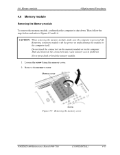
...Memory cover Screw Figure 4-5 Removing the memory cover PORTÉGÉ A600 Maintenance Manual (960-710) [CONFIDENTIAL] 4-15 Remove the memory cover. 4.6 Memory module 4 Replacement Procedures 4.6 Memory module Removing the Memory module To remove the memory module, confirm that the computer is powered off. Removing a memory module with the power on the computer. CAUTION: When removing the memory module, make sure the computer is shut down. Dust and stains on the connectors may cause memory access problems. Never press hard or bend the memory module. 1. Loosen the screw fixing...
...Memory cover Screw Figure 4-5 Removing the memory cover PORTÉGÉ A600 Maintenance Manual (960-710) [CONFIDENTIAL] 4-15 Remove the memory cover. 4.6 Memory module 4 Replacement Procedures 4.6 Memory module Removing the Memory module To remove the memory module, confirm that the computer is powered off. Removing a memory module with the power on the computer. CAUTION: When removing the memory module, make sure the computer is shut down. Dust and stains on the connectors may cause memory access problems. Never press hard or bend the memory module. 1. Loosen the screw fixing...


