Maintenance Manual
Page 8
4.4 Memory Card 4.5 HDD 4.6 Expansion Memory 4.7 Optical Drive Module 4.8 Optical Drive 4.9 Keyboard 4.10 Display Assembly 4.11 Display Mask 4.12 FL Inverter Board 4.13 LCD Module 4.14 WLAN antennas 4.15 Camera and Microphone 4.16 Bluetooth module viii [CONFIDENTIAL] Satellite A200 Series Maintenance Manual
4.4 Memory Card 4.5 HDD 4.6 Expansion Memory 4.7 Optical Drive Module 4.8 Optical Drive 4.9 Keyboard 4.10 Display Assembly 4.11 Display Mask 4.12 FL Inverter Board 4.13 LCD Module 4.14 WLAN antennas 4.15 Camera and Microphone 4.16 Bluetooth module viii [CONFIDENTIAL] Satellite A200 Series Maintenance Manual
Maintenance Manual
Page 46
...still exists, perform Check 3. Check 3 Replace the LCD module with a new one and test display again. Check 2 Replace the FL inverter board with a new one . Check 4 Replace the LCD/FL cable with a new one and test display again. Replace it with another...test display again. Satellite A200/A205/Pro A200 Series Maintenance Manual 16 [CONFIDENTIAL] Refer to Chapter 4, Replacement Procedures, for instructions on how to the display circuits. 2 Troubleshooting Procedures Procedure 3 Connector and replacement check The FL inverter board, LCD module, and system board are connected to...
...still exists, perform Check 3. Check 3 Replace the LCD module with a new one and test display again. Check 2 Replace the FL inverter board with a new one . Check 4 Replace the LCD/FL cable with a new one and test display again. Replace it with another...test display again. Satellite A200/A205/Pro A200 Series Maintenance Manual 16 [CONFIDENTIAL] Refer to Chapter 4, Replacement Procedures, for instructions on how to the display circuits. 2 Troubleshooting Procedures Procedure 3 Connector and replacement check The FL inverter board, LCD module, and system board are connected to...
Maintenance Manual
Page 115
... 4.7 Optical Drive Module 4-21 4.8 Optical Drive...4-23 4.9 Keyboard ...4-25 4.10 Display Assembly 4-28 4.11 Display Mask ...4-33 4.12 FL Inverter Board 4-35 4.13 LCD Module ...4-37 4.14 WLAN antennas 4-40 4.15 Camera and Microphone 4-41 4.16 Bluetooth module 4-43 4.17 Touch Pad... Fingerprint Module 4-47 4.19 Speakers ...4-49 4.20 Function Button Board 4-51 4.21 USB Board ...4-53 4.22 MDC Card...4-55 4.23 Wireless Module 4-57 4.24 System Fan ...4-58 4.25 System Board ...4-60 4.26 VGA Board ...4-63 4.27 CPU ...4-66 Minnesota 10M/10MG Series Maintenance Manual 4-i
... 4.7 Optical Drive Module 4-21 4.8 Optical Drive...4-23 4.9 Keyboard ...4-25 4.10 Display Assembly 4-28 4.11 Display Mask ...4-33 4.12 FL Inverter Board 4-35 4.13 LCD Module ...4-37 4.14 WLAN antennas 4-40 4.15 Camera and Microphone 4-41 4.16 Bluetooth module 4-43 4.17 Touch Pad... Fingerprint Module 4-47 4.19 Speakers ...4-49 4.20 Function Button Board 4-51 4.21 USB Board ...4-53 4.22 MDC Card...4-55 4.23 Wireless Module 4-57 4.24 System Fan ...4-58 4.25 System Board ...4-60 4.26 VGA Board ...4-63 4.27 CPU ...4-66 Minnesota 10M/10MG Series Maintenance Manual 4-i
Maintenance Manual
Page 117
...65 Figure 4-66 Removing CRT module screws and display assembly 4-30 Removing the display assembly 4-31 Removing the rubber pads 4-33 Removing the display mask screws 4-33 Removing the display mask 4-34 Removing the screw 4-35 Removing the connectors 4-35 Removing the FL inverter board 4-36 ... speaker cables 4-49 Removing the speakers 4-50 Removing the Function Button Board screws 4-51 Removing the Function Button Board 4-51 Removing the USB board screw 4-53 Removing the USB board cable 4-53 Removing the USB board 4-54 Removing the MDC card screws 4-55 Minnesota 10M/10MG Series ...
...65 Figure 4-66 Removing CRT module screws and display assembly 4-30 Removing the display assembly 4-31 Removing the rubber pads 4-33 Removing the display mask screws 4-33 Removing the display mask 4-34 Removing the screw 4-35 Removing the connectors 4-35 Removing the FL inverter board 4-36 ... speaker cables 4-49 Removing the speakers 4-50 Removing the Function Button Board screws 4-51 Removing the Function Button Board 4-51 Removing the USB board screw 4-53 Removing the USB board cable 4-53 Removing the USB board 4-54 Removing the MDC card screws 4-55 Minnesota 10M/10MG Series ...
Maintenance Manual
Page 119
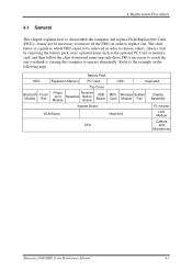
... HDD Expansion Memory PC Card ODD Keyboard Top Cover Bluetooth Touch Module Pad Finger print Module Function Speakers Button Board USB Board MDC Wireless System Card Module Fan Display Assembly System Board FL Inverter VGA Board Heat Sink LCD Module CPU Camera and Microphone Minnesota 10M/10MG Series Maintenance Manual 4-1 It may not be removed...
... HDD Expansion Memory PC Card ODD Keyboard Top Cover Bluetooth Touch Module Pad Finger print Module Function Speakers Button Board USB Board MDC Wireless System Card Module Fan Display Assembly System Board FL Inverter VGA Board Heat Sink LCD Module CPU Camera and Microphone Minnesota 10M/10MG Series Maintenance Manual 4-1 It may not be removed...
Maintenance Manual
Page 120
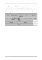
... HDD Expansion Memory PC Card ODD Keyboard Top Cover Bluetooth Touch Module Pad Finger print Module Function Speakers Button Board USB Board MDC Wireless System Card Module Fan Display Assembly System Board FL Inverter VGA Board Heat Sink LCD Module CPU Camera and Microphone 4-2 Minnesota 10M/10MG Series Maintenance Manual Always start the disassembly process...
... HDD Expansion Memory PC Card ODD Keyboard Top Cover Bluetooth Touch Module Pad Finger print Module Function Speakers Button Board USB Board MDC Wireless System Card Module Fan Display Assembly System Board FL Inverter VGA Board Heat Sink LCD Module CPU Camera and Microphone 4-2 Minnesota 10M/10MG Series Maintenance Manual Always start the disassembly process...
Maintenance Manual
Page 153
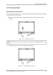
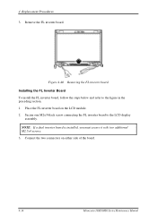
4 Replacement Procedures 4.12 FL Inverter Board Removing the FL Inverter Board To remove the FL inverter board, first remove the battery pack, display assembly, and display mask; then follow the steps below. 1. Disconnect the two connectors on either side of the board. Figure 4-38 Removing the screw NOTE: If a dual inverter board is installed, you must remove two additional M2.5x4 screws. 2. Figure 4-39 Removing the connectors Minnesota 10M/10MG Series Maintenance Manual 4-35 Remove the M2x3 black screw securing the FL inverter board to the LCD display assembly.
4 Replacement Procedures 4.12 FL Inverter Board Removing the FL Inverter Board To remove the FL inverter board, first remove the battery pack, display assembly, and display mask; then follow the steps below. 1. Disconnect the two connectors on either side of the board. Figure 4-38 Removing the screw NOTE: If a dual inverter board is installed, you must remove two additional M2.5x4 screws. 2. Figure 4-39 Removing the connectors Minnesota 10M/10MG Series Maintenance Manual 4-35 Remove the M2x3 black screw securing the FL inverter board to the LCD display assembly.
Maintenance Manual
Page 154
... LCD module. 2. Figure 4-40 Removing the FL inverter board Installing the FL Inverter Board To install the FL inverter board, follow the steps below and refer to the LCD display assembly. Secure one M2x3 black screw connecting the FL inverter board to the figure in the preceding section. 1. NOTE: If a dual inverter board is installed, you must secure it with...
... LCD module. 2. Figure 4-40 Removing the FL inverter board Installing the FL Inverter Board To install the FL inverter board, follow the steps below and refer to the LCD display assembly. Secure one M2x3 black screw connecting the FL inverter board to the figure in the preceding section. 1. NOTE: If a dual inverter board is installed, you must secure it with...

Maintenance Manual
Page 155
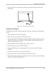
Figure 4-42 Removing the LCD Module Minnesota 10M/10MG Series Maintenance Manual 4-37 Remove four M2.5x4 screws securing the top chassis to the LCD module, and two M2.5x5 screws securing the hinges to the LCD module. Figure 4-41 Removing the LCD Module 2. 4 Replacement Procedures 4.13 LCD Module Removing the LCD Module To remove the LCD module, first remove the display assembly, display mask, and FL inverter board and then follow the steps below. 1. Unhook all cables from the fasteners around the edge of the top chassis.
Figure 4-42 Removing the LCD Module Minnesota 10M/10MG Series Maintenance Manual 4-37 Remove four M2.5x4 screws securing the top chassis to the LCD module, and two M2.5x5 screws securing the hinges to the LCD module. Figure 4-41 Removing the LCD Module 2. 4 Replacement Procedures 4.13 LCD Module Removing the LCD Module To remove the LCD module, first remove the display assembly, display mask, and FL inverter board and then follow the steps below. 1. Unhook all cables from the fasteners around the edge of the top chassis.
Maintenance Manual
Page 157
...the LVDS cable Installing the LCD Module To install the LCD module, follow the steps below and refer to the LCD module. 2. Place the FL inverter board on either side of the LCD display casing 3. 4 Replacement Procedures 5. Detach the LVDS cable. Note the L and R markings to the LCD ...display assembly. 7. Secure one M2x3 black screw connecting the FL inverter board to make sure that the bracket arms are outside of the board. 8. Secure the top chassis to the LCD module with six M2x3 black screws.
...the LVDS cable Installing the LCD Module To install the LCD module, follow the steps below and refer to the LCD module. 2. Place the FL inverter board on either side of the LCD display casing 3. 4 Replacement Procedures 5. Detach the LVDS cable. Note the L and R markings to the LCD ...display assembly. 7. Secure one M2x3 black screw connecting the FL inverter board to make sure that the bracket arms are outside of the board. 8. Secure the top chassis to the LCD module with six M2x3 black screws.
Maintenance Manual
Page 158
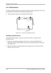
... WLAN cable to the lower right corner. 2. 4 Replacement Procedures 4.14 WLAN antennas To remove the WLAN antennas, first remove the display assembly, display mask, FL inverter board and the LCD display module.
... WLAN cable to the lower right corner. 2. 4 Replacement Procedures 4.14 WLAN antennas To remove the WLAN antennas, first remove the display assembly, display mask, FL inverter board and the LCD display module.
Maintenance Manual
Page 159
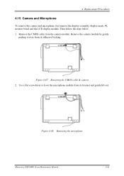
Remove the camera module by gently peeling it away from its bracket and gently lift out. Use a flat screwdriver to lever the microphone module from the camera module. Figure 4-47 Removing the CMOS cable & camera 2. Then follow the steps below. 1. 4 Replacement Procedures 4.15 Camera and Microphone To remove the camera and microphone, first remove the display assembly, display mask, FL inverter board and the LCD display module. Figure 4-48 Removing the microphone Minnesota 10M/10MG Series Maintenance Manual 4-41 Remove the CMOS cable from its adhesive backing.
Remove the camera module by gently peeling it away from its bracket and gently lift out. Use a flat screwdriver to lever the microphone module from the camera module. Figure 4-47 Removing the CMOS cable & camera 2. Then follow the steps below. 1. 4 Replacement Procedures 4.15 Camera and Microphone To remove the camera and microphone, first remove the display assembly, display mask, FL inverter board and the LCD display module. Figure 4-48 Removing the microphone Minnesota 10M/10MG Series Maintenance Manual 4-41 Remove the CMOS cable from its adhesive backing.
Maintenance Manual
Page 240
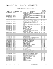
... ASSY (R/L) TO COVER SUB ASSY 2.5~3.0 kg (LCD HINGE SIDE) 2.5~3.0 kg INVERTER TO COVER SUB ASSY (SINGLE 2.5~3.0 kg LAMP) LCD HINGE WALL TO LCD COVER 2.5~3.0 kg INVERTER BRACKET TO COVER SUB ASSY 2.5~3.0 kg (DUAL LAMP) / LCD HINGE WALL TO... CARD TO MB 2.5~3.0 kg ROBSON CARD TO MB 2.5~3.0 kg VGA BOARD TO MB 2.5~3.0 kg CPU SINK ASSY TO CPU PLATE STANDOFF 2.5~3.0 kg VGA SINK ASSY TO VGA BOARD 2.5~3.0 kg HDD BRACKET TO HDD (MAIN) 2.5~3.0 kg HDD BRACKET ...2.5~3.0 kg LOW TO UP 2.5~3.0 kg FAN ASSY TO LOWER 2.5~3.0 kg Satellite A200 Series Maintenance Manual [CONFIDENTIAL] F-1
... ASSY (R/L) TO COVER SUB ASSY 2.5~3.0 kg (LCD HINGE SIDE) 2.5~3.0 kg INVERTER TO COVER SUB ASSY (SINGLE 2.5~3.0 kg LAMP) LCD HINGE WALL TO LCD COVER 2.5~3.0 kg INVERTER BRACKET TO COVER SUB ASSY 2.5~3.0 kg (DUAL LAMP) / LCD HINGE WALL TO... CARD TO MB 2.5~3.0 kg ROBSON CARD TO MB 2.5~3.0 kg VGA BOARD TO MB 2.5~3.0 kg CPU SINK ASSY TO CPU PLATE STANDOFF 2.5~3.0 kg VGA SINK ASSY TO VGA BOARD 2.5~3.0 kg HDD BRACKET TO HDD (MAIN) 2.5~3.0 kg HDD BRACKET ...2.5~3.0 kg LOW TO UP 2.5~3.0 kg FAN ASSY TO LOWER 2.5~3.0 kg Satellite A200 Series Maintenance Manual [CONFIDENTIAL] F-1
Maintenance Manual
Page 241
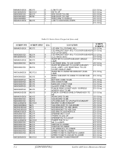
...LCD BRACKET ASSY (R/L) TO COVER SUB ASSY 2.5~3.0 kg (LCD HINGE SIDE) 2.5~3.0 kg INVERTER TO COVER SUB ASSY (SINGLE 2.5~3.0 kg LAMP) LCD HINGE WALL TO LCD COVER 2.5~3.0 kg INVERTER BRACKET TO COVER SUB ASSY 2.5~3.0 kg (DUAL LAMP) / LCD HINGE WALL TO LCD... TO MB PCMCIA / EXPRESS SHIELD FRAME ASSY TO 2.5~3.0 kg MB WLAN CARD TO MB 2.5~3.0 kg VGA BOARD TO MB 2.5~3.0 kg CPU SINK ASSY TO CPU PLATE STANDOFF 2.5~3.0 kg NB SINK TO MB STANDOFF 2.5~3.0 kg VGA SINK ... BD TO LOWER 2.5~3.0 kg MDC MODEN TO MB STANDOFF 2.5~3.0 kg F-2 [CONFIDENTIAL] Satellite A200 Series Maintenance Manual
...LCD BRACKET ASSY (R/L) TO COVER SUB ASSY 2.5~3.0 kg (LCD HINGE SIDE) 2.5~3.0 kg INVERTER TO COVER SUB ASSY (SINGLE 2.5~3.0 kg LAMP) LCD HINGE WALL TO LCD COVER 2.5~3.0 kg INVERTER BRACKET TO COVER SUB ASSY 2.5~3.0 kg (DUAL LAMP) / LCD HINGE WALL TO LCD... TO MB PCMCIA / EXPRESS SHIELD FRAME ASSY TO 2.5~3.0 kg MB WLAN CARD TO MB 2.5~3.0 kg VGA BOARD TO MB 2.5~3.0 kg CPU SINK ASSY TO CPU PLATE STANDOFF 2.5~3.0 kg NB SINK TO MB STANDOFF 2.5~3.0 kg VGA SINK ... BD TO LOWER 2.5~3.0 kg MDC MODEN TO MB STANDOFF 2.5~3.0 kg F-2 [CONFIDENTIAL] Satellite A200 Series Maintenance Manual


