
Toshiba Online Users Guide for Satellite A20/A25
Page 47
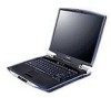
Underside CPU cooling fan Battery pack Hard disk drive Battery release latch The hard disk drive is currently playing. Press the button again to play a CD or DVD. If you have set a password for logging onto your system, your computer will start up and you will need to log on before being able to eject the disc. Finding Your Way Around Underside 47 The stop/eject button stops a disc that is the computer's permanent data storage device.
Underside CPU cooling fan Battery pack Hard disk drive Battery release latch The hard disk drive is currently playing. Press the button again to play a CD or DVD. If you have set a password for logging onto your system, your computer will start up and you will need to log on before being able to eject the disc. Finding Your Way Around Underside 47 The stop/eject button stops a disc that is the computer's permanent data storage device.
Toshiba Online Users Guide for Satellite A20/A25
Page 48
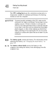
...on surfaces with objects that can block the air intake, preventing air from the computer case. 48 Finding Your Way Around Underside The CPU cooling fan keeps the central processing unit at a lower performance level or cause the computer to the computer, preventing the battery from dislodging from reaching the... CPU. To prevent possible overheating of the CPU, make sure the cooling fan's air intake is blocked, it could cause the CPU to run at a temperature suitable for optimum performance by the cooling...
...on surfaces with objects that can block the air intake, preventing air from the computer case. 48 Finding Your Way Around Underside The CPU cooling fan keeps the central processing unit at a lower performance level or cause the computer to the computer, preventing the battery from dislodging from reaching the... CPU. To prevent possible overheating of the CPU, make sure the cooling fan's air intake is blocked, it could cause the CPU to run at a temperature suitable for optimum performance by the cooling...

Maintenance Manual
Page 9
...4.2 Battery Pack...4-9 4.3 Optional PC Card...4-11 4.4 Optional SD Card...4-13 4.5 HDD ...4-14 4.6 Modem Daughter Card 4-18 4.7 Slim Select Bay Module 4-20 4.8 Cooling Fan...4-24 4.9 CPU...4-27 4.10 Keyboard ...4-32 4.11 Memory Module...4-36 4.12 Wireless LAN Card 4-38 4.13 Bluetooth...4-41 4.14 Switch Board...4-43 4.15 Top Cover... USB Board...4-52 4.19 Sound Board ...4-54 4.20 RTC Battery...4-56 4.21 DC-IN Jack ...4-58 4.22 System Board ...4-59 4.23 Sub Fan...4-61 4.24 PC Card Slot...4-63 4.25 Speakers ...4-65 4.26 Touch Pad Switch...4-67 4.27 Display Mask...4-68 4.28 FL Inverter ...4-70 4....
...4.2 Battery Pack...4-9 4.3 Optional PC Card...4-11 4.4 Optional SD Card...4-13 4.5 HDD ...4-14 4.6 Modem Daughter Card 4-18 4.7 Slim Select Bay Module 4-20 4.8 Cooling Fan...4-24 4.9 CPU...4-27 4.10 Keyboard ...4-32 4.11 Memory Module...4-36 4.12 Wireless LAN Card 4-38 4.13 Bluetooth...4-41 4.14 Switch Board...4-43 4.15 Top Cover... USB Board...4-52 4.19 Sound Board ...4-54 4.20 RTC Battery...4-56 4.21 DC-IN Jack ...4-58 4.22 System Board ...4-59 4.23 Sub Fan...4-61 4.24 PC Card Slot...4-63 4.25 Speakers ...4-65 4.26 Touch Pad Switch...4-67 4.27 Display Mask...4-68 4.28 FL Inverter ...4-70 4....
Maintenance Manual
Page 41
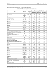
...NO NO NO USB Power E5V 5.0 YES NO NO M1672,PC-Card(s) B5V 5.0 YES NO NO M1535+,BIOS,HDD,Mini PCI,Keyboard,TouchPad,FAN,LEDs P5V 5.0 NO NO NO ODD CD-E5V 5.0 YES YES NO FL-inv FL-P5V 5.0 NO NO NO SD card SD-B3V ...3.3 YES NO NO MDC CRT MDC-B3V 3.3 YES NO NO DDC-P5V 5.0 NO NO NO Sound Sound Sound Pull-ups FAN EC/KBC,M1535+,OZ168 M1535+,OZ168,LEDs,Battery PSC RTC(CLK 32kHz) SND-E5V CDA4R7E4V A4R7-P4V 15-EBV FANVCC S3V S5V MCV R3V ... YES YES NO NO NO YES YES YES YES NO NO NO NO NO NO NO NO YES Satellite A20 Maintenance Manual (960-444) 1-27
...NO NO NO USB Power E5V 5.0 YES NO NO M1672,PC-Card(s) B5V 5.0 YES NO NO M1535+,BIOS,HDD,Mini PCI,Keyboard,TouchPad,FAN,LEDs P5V 5.0 NO NO NO ODD CD-E5V 5.0 YES YES NO FL-inv FL-P5V 5.0 NO NO NO SD card SD-B3V ...3.3 YES NO NO MDC CRT MDC-B3V 3.3 YES NO NO DDC-P5V 5.0 NO NO NO Sound Sound Sound Pull-ups FAN EC/KBC,M1535+,OZ168 M1535+,OZ168,LEDs,Battery PSC RTC(CLK 32kHz) SND-E5V CDA4R7E4V A4R7-P4V 15-EBV FANVCC S3V S5V MCV R3V ... YES YES NO NO NO YES YES YES YES NO NO NO NO NO NO NO NO YES Satellite A20 Maintenance Manual (960-444) 1-27

Maintenance Manual
Page 74
...configuration Enable L1 cache Memory clear Transition to real mode, coping BIOS on RAM Storing key scan code Setting TASK_1ms_TSC Display initialization FAN control Sound controller initialization (for beep) Enabling system speaker Disabling mute Setting the volume to max Display of message (EC/KBC... the route directory by one sector Searching the entry of "CHGBIOSA.EXE"/ "CHGFIRM.EXE" Executing "CHGBIOSA.EXE"/ "CHGFIRM.EXE" 2-24 Satellite A20 Maintenance Manual (960-444) Key input when an error is defined.) Setting parameters for 2DD (720KB), setting transmission rate Reading the first ...
...configuration Enable L1 cache Memory clear Transition to real mode, coping BIOS on RAM Storing key scan code Setting TASK_1ms_TSC Display initialization FAN control Sound controller initialization (for beep) Enabling system speaker Disabling mute Setting the volume to max Display of message (EC/KBC... the route directory by one sector Searching the entry of "CHGBIOSA.EXE"/ "CHGFIRM.EXE" Executing "CHGBIOSA.EXE"/ "CHGFIRM.EXE" 2-24 Satellite A20 Maintenance Manual (960-444) Key input when an error is defined.) Setting parameters for 2DD (720KB), setting transmission rate Reading the first ...
Maintenance Manual
Page 118
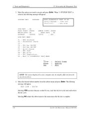
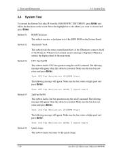
... : YES/NO Selecting YES increases the pass counter by your computer may be slightly different from the subtest menu and press Enter. CPU Fan ON/OFF 05 - 2nd Fan ON/OFF 06 - Selecting NO returns the subtest menu to the main menu after the test is selected, the following message will appear... restarts the test cycle. Exit to execute and press Enter. DMI write 09 - Thermister Check 03 04 - ROM checksum 02 - When "1-SYSTEM TEST" is complete. 3-6 Satellite A20 Maintenance Manual (960-444)
... : YES/NO Selecting YES increases the pass counter by your computer may be slightly different from the subtest menu and press Enter. CPU Fan ON/OFF 05 - 2nd Fan ON/OFF 06 - Selecting NO returns the subtest menu to the main menu after the test is selected, the following message will appear... restarts the test cycle. Exit to execute and press Enter. DMI write 09 - Thermister Check 03 04 - ROM checksum 02 - When "1-SYSTEM TEST" is complete. 3-6 Satellite A20 Maintenance Manual (960-444)

Maintenance Manual
Page 120
... 05 08 01 02 03 04 05 06 07 01 02 03 04 05 01 02 03 Subtest Name ROM checksum Thermister Check CPU Fan ON/OFF 2nd Fan ON/OFF Quick charge DMI read DMI write CPU Temperature Conventional memory Protected mode Cache memory L2 cache memory Stress Pressed key display... for LCD "H" pattern display LCD Brightness Sequential read Sequential read/write Random address/data Write specified address Read specified address Ripple pattern Function Wrap around 3-8 Satellite A20 Maintenance Manual (960-444)
... 05 08 01 02 03 04 05 06 07 01 02 03 04 05 01 02 03 Subtest Name ROM checksum Thermister Check CPU Fan ON/OFF 2nd Fan ON/OFF Quick charge DMI read DMI write CPU Temperature Conventional memory Protected mode Cache memory L2 cache memory Stress Pressed key display... for LCD "H" pattern display LCD Brightness Sequential read Sequential read/write Random address/data Write specified address Read specified address Ripple pattern Function Wrap around 3-8 Satellite A20 Maintenance Manual (960-444)
Maintenance Manual
Page 122
...error message is executed. Make sure the fan does not rotate and press Enter. When it is executed. Test CPU Fan Revolution LEVEL 5 speed start Subtest 06 Quick charge This subtest checks the status for the quick charge. 3-10 Satellite A20 Maintenance Manual (960-444) Subtest 01... ROM Checksum This subtest executes a checksum test of the PS micon. Test 2nd Fan Revolution 0000RPM Start The following message will appear when this subtest is displayed...
...error message is executed. Make sure the fan does not rotate and press Enter. When it is executed. Test CPU Fan Revolution LEVEL 5 speed start Subtest 06 Quick charge This subtest checks the status for the quick charge. 3-10 Satellite A20 Maintenance Manual (960-444) Subtest 01... ROM Checksum This subtest executes a checksum test of the PS micon. Test 2nd Fan Revolution 0000RPM Start The following message will appear when this subtest is displayed...
Maintenance Manual
Page 190
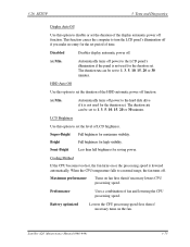
... turns off power to set to a normal range, the fan turns off . The duration xx can be set the level of LCD brightness. When the CPU temperature falls to 1, 3, 5, 10, 15, 20 or 30 minutes. Satellite A20 Maintenance Manual (960-444) 3-75 Super-Bright Full brightness ...for the duration set period of fan and lowering the CPU processing speed. Cooling Method If the CPU becomes too hot, the...
... turns off power to set to a normal range, the fan turns off . The duration xx can be set the level of LCD brightness. When the CPU temperature falls to 1, 3, 5, 10, 15, 20 or 30 minutes. Satellite A20 Maintenance Manual (960-444) 3-75 Super-Bright Full brightness ...for the duration set period of fan and lowering the CPU processing speed. Cooling Method If the CPU becomes too hot, the...
Maintenance Manual
Page 203
... General...4-1 4.2 Battery Pack...4-8 4.3 Optional PC Card...4-10 4.4 Optional SD Card...4-12 4.5 HDD ...4-13 4.6 Modem Daughter Card 4-17 4.7 ODD ...4-19 4.8 Cooling Fan...4-23 4.9 CPU...4-26 4.10 Keyboard ...4-31 4.11 Memory Module...4-35 4.12 Wireless LAN Card 4-37 4.13 Bluetooth...4-40 4.14 Top Cover with Display Assembly 4-42...FIR Board ...4-49 4.18 Sound Board ...4-51 4.19 RTC Battery...4-53 4.20 DC-IN Jack ...4-55 4.21 System Board ...4-56 4.22 Sub Fan...4-58 4.23 PC Card Slot...4-60 4.24 Speakers ...4-62 4.25 Touch Pad Switch...4-64 4.26 Display Mask...4-65 4.27 FL Inverter ...4-67 4....
... General...4-1 4.2 Battery Pack...4-8 4.3 Optional PC Card...4-10 4.4 Optional SD Card...4-12 4.5 HDD ...4-13 4.6 Modem Daughter Card 4-17 4.7 ODD ...4-19 4.8 Cooling Fan...4-23 4.9 CPU...4-26 4.10 Keyboard ...4-31 4.11 Memory Module...4-35 4.12 Wireless LAN Card 4-37 4.13 Bluetooth...4-40 4.14 Top Cover with Display Assembly 4-42...FIR Board ...4-49 4.18 Sound Board ...4-51 4.19 RTC Battery...4-53 4.20 DC-IN Jack ...4-55 4.21 System Board ...4-56 4.22 Sub Fan...4-58 4.23 PC Card Slot...4-60 4.24 Speakers ...4-62 4.25 Touch Pad Switch...4-64 4.26 Display Mask...4-65 4.27 FL Inverter ...4-67 4....
Maintenance Manual
Page 204
...daughter card 4-17 Removing the ODD 4-20 Disassembling the ODD 4-21 Removing the Cooling fan module 4-24 Removing the Fin cover 4-26 Removing the Fin 4-27 Unlocking the CPU 4-28 4-iv Satellite A20 Maintenance Manual (960-444) 4 Replacement Procedures 4.29 Wireless LAN Antenna/Bluetooth Antenna/...SXGA+ Samsung Fluorescent Lamp 4-145 4.30.7 Replacing the 15.0-inch SXGA+ Sharp Fluorescent Lamp 4-155 4.30.8 Replacing the 14.1-inch XGA TOSHIBA Fluorescent Lamp 4-180 4.30.9 Replacing the 14.1-inch XGA Sharp Fluorescent Lamp 4-192 4.30.10 Replacing the 14.1-inch XGA Samsung Fluorescent...
...daughter card 4-17 Removing the ODD 4-20 Disassembling the ODD 4-21 Removing the Cooling fan module 4-24 Removing the Fin cover 4-26 Removing the Fin 4-27 Unlocking the CPU 4-28 4-iv Satellite A20 Maintenance Manual (960-444) 4 Replacement Procedures 4.29 Wireless LAN Antenna/Bluetooth Antenna/...SXGA+ Samsung Fluorescent Lamp 4-145 4.30.7 Replacing the 15.0-inch SXGA+ Sharp Fluorescent Lamp 4-155 4.30.8 Replacing the 14.1-inch XGA TOSHIBA Fluorescent Lamp 4-180 4.30.9 Replacing the 14.1-inch XGA Sharp Fluorescent Lamp 4-192 4.30.10 Replacing the 14.1-inch XGA Samsung Fluorescent...
Maintenance Manual
Page 205
...Removing the Sound board 4-51 Removing the RTC battery 4-54 Removing the DC-IN jack 4-55 Removing the System board 4-56 Removing the Sub Fan 4-58 Removing the PC card slot 4-60 Removing the Speakers 4-62 Removing the Side cover 4-63 Removing the Touch pad switch 4-64 Removing ...the Display mask (1 4-65 Removing the Display mask (2 4-66 Removing the FL inverter 4-67 Removing the LCD module (1 4-70 Removing the LCD module (2 4-71 Removing the Latch assembly 4-73 Removing the Wireless LAN...
...Removing the Sound board 4-51 Removing the RTC battery 4-54 Removing the DC-IN jack 4-55 Removing the System board 4-56 Removing the Sub Fan 4-58 Removing the PC card slot 4-60 Removing the Speakers 4-62 Removing the Side cover 4-63 Removing the Touch pad switch 4-64 Removing ...the Display mask (1 4-65 Removing the Display mask (2 4-66 Removing the FL inverter 4-67 Removing the LCD module (1 4-70 Removing the LCD module (2 4-71 Removing the Latch assembly 4-73 Removing the Wireless LAN...

Maintenance Manual
Page 236
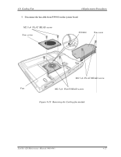
...attached to the back of the computer. Wait for the fan to prevent dust or dirt from entering inside of the fan cover to cool before removing it. Remove the following screws securing the fan cover and remove the fan cover. • M2.5×4 FLAT HEAD screw ×...Replacement Procedures 4.8 Cooling Fan 4.8 Cooling Fan Removing the Cooling Fan To remove the cooling fan, follow the steps below and refer to the cooling fan module. 1. Do not touch the fan rotor or fan blades or apply impact to figure 4-10. Remove the cooling fan module. 4-26 Satellite A20 Maintenance Manual (960-444...
...attached to the back of the computer. Wait for the fan to prevent dust or dirt from entering inside of the fan cover to cool before removing it. Remove the following screws securing the fan cover and remove the fan cover. • M2.5×4 FLAT HEAD screw ×...Replacement Procedures 4.8 Cooling Fan 4.8 Cooling Fan Removing the Cooling Fan To remove the cooling fan, follow the steps below and refer to the cooling fan module. 1. Do not touch the fan rotor or fan blades or apply impact to figure 4-10. Remove the cooling fan module. 4-26 Satellite A20 Maintenance Manual (960-444...
Maintenance Manual
Page 237
M2.5 ×4 FLAT HEAD screw Fan cover PJ9900 Fin cover M2.5×6 FLAT HEAD screw Fan M2.5×6 FLAT HEAD screw Figure 4-10 Removing the Cooling fan module Satellite A20 Maintenance Manual (960-444) 4-27 Disconnect the fan cable from PJ9900 on the system board. 4.8 Cooling Fan 4 Replacement Procedures 5.
M2.5 ×4 FLAT HEAD screw Fan cover PJ9900 Fin cover M2.5×6 FLAT HEAD screw Fan M2.5×6 FLAT HEAD screw Figure 4-10 Removing the Cooling fan module Satellite A20 Maintenance Manual (960-444) 4-27 Disconnect the fan cable from PJ9900 on the system board. 4.8 Cooling Fan 4 Replacement Procedures 5.

Maintenance Manual
Page 238
... screws. • M2.5×6 FLAT HEAD screw ×2 3. Seat the cooling fan. 2. Place the fin cover and secure it with the following screws. • M2.5×6 FLAT HEAD screw ×2 4-28 Satellite A20 Maintenance Manual (960-444) CAUTION: Before installing the fan cover, vacuum off dust or dirt on the indentation of the filter...
... screws. • M2.5×6 FLAT HEAD screw ×2 3. Seat the cooling fan. 2. Place the fin cover and secure it with the following screws. • M2.5×6 FLAT HEAD screw ×2 4-28 Satellite A20 Maintenance Manual (960-444) CAUTION: Before installing the fan cover, vacuum off dust or dirt on the indentation of the filter...

Maintenance Manual
Page 239
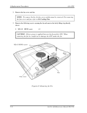
4.9 CPU 4 Replacement Procedures 4.9 CPU Removing the CPU To remove the CPU, follow the steps below and refer to figures 4-11 to 4-14. Apply new grease when installing. 1. Remove the following screw securing the fin cover and remove the fin cover. • M2.5×6 FLAT HEAD screw ×2 Fin cover M2.5×6 FLAT HEAD screw Figure 4-11 Removing the Fin cover Satellite A20 Maintenance Manual (960-444) 4-29 CAUTION: When you remove the CPU, wipe the grease off of the bottom of the heat sink, bottom of the cooling fan and top of the CPU.
4.9 CPU 4 Replacement Procedures 4.9 CPU Removing the CPU To remove the CPU, follow the steps below and refer to figures 4-11 to 4-14. Apply new grease when installing. 1. Remove the following screw securing the fin cover and remove the fin cover. • M2.5×6 FLAT HEAD screw ×2 Fin cover M2.5×6 FLAT HEAD screw Figure 4-11 Removing the Fin cover Satellite A20 Maintenance Manual (960-444) 4-29 CAUTION: When you remove the CPU, wipe the grease off of the bottom of the heat sink, bottom of the cooling fan and top of the CPU.
Maintenance Manual
Page 240
Remove the fan cover and fan. M2×18 BIND screw Fin Fan cover Figure4-12 Removing the Fin 4-30 Satellite A20 Maintenance Manual (960-444) For removing the fan cover and fan, refer to damage the CPU under the fin. When removing the fin, be removed. Remove the following screws securing the fin and remove the fin... above. • M2×18 BIND screw ×2 CAUTION: Silicon grease is applied between the fin and the CPU. NOTE: To remove the fin, the fan cover and fan must be careful not to 4.8 Cooling...
Remove the fan cover and fan. M2×18 BIND screw Fin Fan cover Figure4-12 Removing the Fin 4-30 Satellite A20 Maintenance Manual (960-444) For removing the fan cover and fan, refer to damage the CPU under the fin. When removing the fin, be removed. Remove the following screws securing the fin and remove the fin... above. • M2×18 BIND screw ×2 CAUTION: Silicon grease is applied between the fin and the CPU. NOTE: To remove the fin, the fan cover and fan must be careful not to 4.8 Cooling...
Maintenance Manual
Page 243
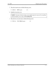
4.9 CPU 4 Replacement Procedures 5. Place the fin cover and secure it with the following screws. • M2×18 BIND screw ×2 6. For installing the fan and fan cover, refer to 4.8 Cooling Fan. 7. Install the fan and fan cover. NOTE: To remove the fin, the fan cover and fan must be removed. Place the fin and secure it with the following screws. • M2.5×6 FLAT HEAD screw ×2 Satellite A20 Maintenance Manual (960-444) 4-33
4.9 CPU 4 Replacement Procedures 5. Place the fin cover and secure it with the following screws. • M2×18 BIND screw ×2 6. For installing the fan and fan cover, refer to 4.8 Cooling Fan. 7. Install the fan and fan cover. NOTE: To remove the fin, the fan cover and fan must be removed. Place the fin and secure it with the following screws. • M2.5×6 FLAT HEAD screw ×2 Satellite A20 Maintenance Manual (960-444) 4-33
Maintenance Manual
Page 257
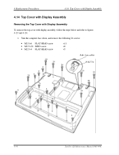
....5×6 FLAT HEAD screw ×11 • M2.5×20 BIND screw ×8 • M2.5×4 FLAT HEAD screw ×5 20 20 20 6 6 20 6 Sub fan cable PJ8770 20 20 6 6 6 6 4 6 4 6 4 6 4 4 20 20 6 4-44 Satellite A20 Maintenance Manual (960-444)
....5×6 FLAT HEAD screw ×11 • M2.5×20 BIND screw ×8 • M2.5×4 FLAT HEAD screw ×5 20 20 20 6 6 20 6 Sub fan cable PJ8770 20 20 6 6 6 6 4 6 4 6 4 6 4 4 20 20 6 4-44 Satellite A20 Maintenance Manual (960-444)
Maintenance Manual
Page 259
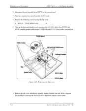
...cover 6. Remove the top cover with Display Assembly 2. Be careful not to damage the wireless LAN or Bluetooth antenna coaxial cables. 4-46 Satellite A20 Maintenance Manual (960-444) 4 Replacement Procedures 4.14 Top Cover with display assembly starting from PJ8770 on the system board. Turn the computer... cables from PJ5600 and PJ5601 and the speaker cables from PJ9512 (red) and PJ9513 (blue) on the system board. 3. Disconnect the sub fan cable from the front side of the computer. Remove the following screws securing the top cover. • M2.5×6 FLAT HEAD screw ×...
...cover 6. Remove the top cover with Display Assembly 2. Be careful not to damage the wireless LAN or Bluetooth antenna coaxial cables. 4-46 Satellite A20 Maintenance Manual (960-444) 4 Replacement Procedures 4.14 Top Cover with display assembly starting from PJ8770 on the system board. Turn the computer... cables from PJ5600 and PJ5601 and the speaker cables from PJ9512 (red) and PJ9513 (blue) on the system board. 3. Disconnect the sub fan cable from the front side of the computer. Remove the following screws securing the top cover. • M2.5×6 FLAT HEAD screw ×...


