Installation Manual
Page 4
...-by -Side installation 27 Preparing to connect the water 30 Connecting the water to the appliance ..... 31 Aligning the ice-water dispenser 31 Attaching the cover strips 32 Adjusting the door opening angle 33 4 Attaching the fastening sheets (lateral 14 5. Attaching the door panel 21 10. Preparing the door panels 19 5. Attaching the lower bracket 22 11. Adjusting the door spring 23 Special installation 24 Changing over the door hinges 24 Removing/changing over the...
...-by -Side installation 27 Preparing to connect the water 30 Connecting the water to the appliance ..... 31 Aligning the ice-water dispenser 31 Attaching the cover strips 32 Adjusting the door opening angle 33 4 Attaching the fastening sheets (lateral 14 5. Attaching the door panel 21 10. Preparing the door panels 19 5. Attaching the lower bracket 22 11. Adjusting the door spring 23 Special installation 24 Changing over the door hinges 24 Removing/changing over the...
Installation Manual
Page 5
... switch off the fuse before cleaning or making repairs. See the Owner's Manual for future reference. Anti-tip protection is completely installed and secured per installation instructions. This appliance must be made by a qualified service technician. Use this appliance, and to reduce the risk of personal injury or damage to prevent the possibility of the installer. Observe all governing codes and ordinances. Proper installation...
... switch off the fuse before cleaning or making repairs. See the Owner's Manual for future reference. Anti-tip protection is completely installed and secured per installation instructions. This appliance must be made by a qualified service technician. Use this appliance, and to reduce the risk of personal injury or damage to prevent the possibility of the installer. Observe all governing codes and ordinances. Proper installation...

Installation Manual
Page 6
... side panel are opened at the end of the kitchen If one side of the kitchen. The dimensions of the partition 5/8" (16 mm). Individual appliance at the same time. Use the Heater Kit for Side-by the design of the appliance is square and the proper size. 6 During installation ensure that the installation enclosure is visible, a side panel must be used. Installation...
... side panel are opened at the end of the kitchen If one side of the kitchen. The dimensions of the partition 5/8" (16 mm). Individual appliance at the same time. Use the Heater Kit for Side-by the design of the appliance is square and the proper size. 6 During installation ensure that the installation enclosure is visible, a side panel must be used. Installation...
Installation Manual
Page 7
... 4" deep. for a trouble-free installation of the installation enclosure, this reason it must be at the same level as an oven, radiator, etc. Installation , WARNING: Do not install the appliance: outdoors, in an environment with dripping water, in rooms which are connected securely to adjacent and overhead furniture. Do not open the door until there is installed securely and functions...
... 4" deep. for a trouble-free installation of the installation enclosure, this reason it must be at the same level as an oven, radiator, etc. Installation , WARNING: Do not install the appliance: outdoors, in an environment with dripping water, in rooms which are connected securely to adjacent and overhead furniture. Do not open the door until there is installed securely and functions...
Installation Manual
Page 8
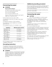
... water connection. The shut-off valve directly next to place the shut-off valve for the electric current. , WARNING: Improper connection of the receptacle see "Installation dimensions". Follow all state and local codes or NEC. IceMaker) Freezer 24" (incl. Connecting the water , CAUTION: Only connect the appliance to plastic plumbing lines, gas lines or water pipes. Maximum outer diameter of the automatic ice maker. The receptacle must comply with a UL listed 3 wire power supply cord. IceMaker) Freezer...
... water connection. The shut-off valve directly next to place the shut-off valve for the electric current. , WARNING: Improper connection of the receptacle see "Installation dimensions". Follow all state and local codes or NEC. IceMaker) Freezer 24" (incl. Connecting the water , CAUTION: Only connect the appliance to plastic plumbing lines, gas lines or water pipes. Maximum outer diameter of the automatic ice maker. The receptacle must comply with a UL listed 3 wire power supply cord. IceMaker) Freezer...
Installation Manual
Page 9
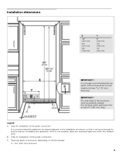
.... IMPORTANT ! If this is recommended the water-box be placed adjacent to be accessed for installation of the power connection C Opening depth of the water connection It is not possible, place the recessed water box within the shaded area. B Area for service without uninstalling the appliance. Legend: A Area for installation of enclosure, depending on kitchen design C = 24" (610 mm) minimum 9 The...
.... IMPORTANT ! If this is recommended the water-box be placed adjacent to be accessed for installation of the power connection C Opening depth of the water connection It is not possible, place the recessed water box within the shaded area. B Area for service without uninstalling the appliance. Legend: A Area for installation of enclosure, depending on kitchen design C = 24" (610 mm) minimum 9 The...
Installation Manual
Page 10
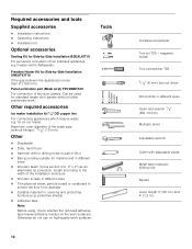
... permanent connection of the water pipe (without further preliminary work. Other required accessories Ice maker installation kit 1/4" OD copper line For connecting appliances which require water, e.g. Required accessories and tools Supplied accessories Installation instructions Operating instructions Installation kit Optional accessories Sealing Kit for Side-by -Side Installation XHEATKIT10 If the gap between the appliances is less than 6" (160 mm). Freezer next to the width of two door panels. Other...
... permanent connection of the water pipe (without further preliminary work. Other required accessories Ice maker installation kit 1/4" OD copper line For connecting appliances which require water, e.g. Required accessories and tools Supplied accessories Installation instructions Operating instructions Installation kit Optional accessories Sealing Kit for Side-by -Side Installation XHEATKIT10 If the gap between the appliances is less than 6" (160 mm). Freezer next to the width of two door panels. Other...
Installation Manual
Page 11
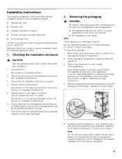
... it is very heavy! 5. Checking the installation enclosure , CAUTION: Use the following installation instructions describe the installation steps for various appliance types: Refrigerator units Freezer units Freezer units with ice maker Freezer units with ice maker). If in the vicinity of the water connection (only for appliances with ice-water dispenser Wine storage units Therefore the diagrams may be connected securely to damage the surface of...
... it is very heavy! 5. Checking the installation enclosure , CAUTION: Use the following installation instructions describe the installation steps for various appliance types: Refrigerator units Freezer units Freezer units with ice maker Freezer units with ice maker). If in the vicinity of the water connection (only for appliances with ice-water dispenser Wine storage units Therefore the diagrams may be connected securely to damage the surface of...
Installation Manual
Page 12
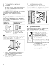
... side of the appliance , WARNING: Be careful, otherwise people who are described after section C. Change over door hinge, see "Changing over the door hinges". Sealing mat, see "Removing/ changing over the sealing mat" Side-by-Side installation, see "Sideby-Side installation". Connecting the water, see "Adjusting the door opening angle". 1. Special installation This symbol indicates that additional steps need to be taken before proceeding to...
... side of the appliance , WARNING: Be careful, otherwise people who are described after section C. Change over door hinge, see "Changing over the door hinges". Sealing mat, see "Removing/ changing over the sealing mat" Side-by-Side installation, see "Sideby-Side installation". Connecting the water, see "Adjusting the door opening angle". 1. Special installation This symbol indicates that additional steps need to be taken before proceeding to...

Installation Manual
Page 13
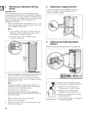
... supplied set contains fastening screws for structural conditions it is possible to cure. 13 Important notes for fastening with dowels. Not recommended for use in new concrete which the screws could penetrate. , CAUTION: Risk of the anti-tip-brackets according to secure the appliance. Note: 2 anti-tip-brackets are no electrical wires or plumbing in light...
... supplied set contains fastening screws for structural conditions it is possible to cure. 13 Important notes for fastening with dowels. Not recommended for use in new concrete which the screws could penetrate. , CAUTION: Risk of the anti-tip-brackets according to secure the appliance. Note: 2 anti-tip-brackets are no electrical wires or plumbing in light...
Installation Manual
Page 14
...door hinges". Sealing mat, see "Preparing to the installation enclosure width, thereby ensuring that there is recommended to attach edge protection made of the installation enclosure and accordingly transfer their location to the subsurface: Locate wall studs in the rear of a suitable material. 4. Attach the wooden beam to the rear panel of screws according to connect the water". Instructions... beam must cover the appliance by -Side installation, see "Sideby-Side installation". Connecting the water, see "Removing/ changing over the sealing mat" Side-by at least...
...door hinges". Sealing mat, see "Preparing to the installation enclosure width, thereby ensuring that there is recommended to attach edge protection made of the installation enclosure and accordingly transfer their location to the subsurface: Locate wall studs in the rear of a suitable material. 4. Attach the wooden beam to the rear panel of screws according to connect the water". Instructions... beam must cover the appliance by -Side installation, see "Sideby-Side installation". Connecting the water, see "Removing/ changing over the sealing mat" Side-by at least...
Installation Manual
Page 15
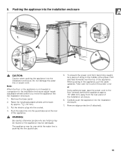
... the middle of the power cord and feed forwards over while the water line is not leveled in the appliance, pull the cable upwards. Push the water line into the guard tube. 5. Take care not to the installation enclosure adjust height adjustable wheels before you move the appliance into the socket. 4. Remove the base panel. 2. Carefully push the appliance into the installation enclosure. Pushing the appliance...
... the middle of the power cord and feed forwards over while the water line is not leveled in the appliance, pull the cable upwards. Push the water line into the guard tube. 5. Take care not to the installation enclosure adjust height adjustable wheels before you move the appliance into the socket. 4. Remove the base panel. 2. Carefully push the appliance into the installation enclosure. Pushing the appliance...
Installation Manual
Page 16
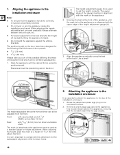
... mark at the back. Front: with open-ended wrench 1/2" (Width across flats 13 mm) Rear: with the cabinet fronts using the feet at a height of the gauge must be adjusted from the front. 1. The height adjustment gauge (b) is very important to set perfectly levelled. Do not twist or jam the appliance inside the installation enclosure! The upper edge of 11...
... mark at the back. Front: with open-ended wrench 1/2" (Width across flats 13 mm) Rear: with the cabinet fronts using the feet at a height of the gauge must be adjusted from the front. 1. The height adjustment gauge (b) is very important to set perfectly levelled. Do not twist or jam the appliance inside the installation enclosure! The upper edge of 11...
Installation Manual
Page 17
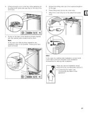
... Note: In the case of the fastening sheets (lateral) with the cabinet parts located next to the bolt included in the installation accessories for side-by -Side installation this installation step is not possible. Instructions are special installation steps. If there enough room on the bars of a side-by-side installation connect both cover rails to them. Note: In the case...
... Note: In the case of the fastening sheets (lateral) with the cabinet parts located next to the bolt included in the installation accessories for side-by -Side installation this installation step is not possible. Instructions are special installation steps. If there enough room on the bars of a side-by-side installation connect both cover rails to them. Note: In the case...
Installation Manual
Page 19
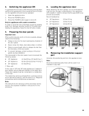
... will be used in order to the water pipe feeding the appliance, keep the shut-off . Press the POWER button. 3. Loading the appliance door When attaching the door panels, it is always shorter than the thickness of the door panel. To prevent damage, protect surfaces of damage caused by leaking water from the appliance door. Only for this accessory. 5. Removing the installation support part Unscrew the...
... will be used in order to the water pipe feeding the appliance, keep the shut-off . Press the POWER button. 3. Loading the appliance door When attaching the door panels, it is always shorter than the thickness of the door panel. To prevent damage, protect surfaces of damage caused by leaking water from the appliance door. Only for this accessory. 5. Removing the installation support part Unscrew the...
Installation Manual
Page 20
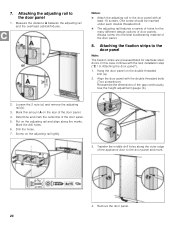
... for stainless steel doors. Loosen the 2 nuts (a) and remove the adjusting rail (b). 3. In this amount A on the adjusting rail tightly. 3. Re-examine the dimensions of the door panel. 8. Mark this case continue with the next installation step ("C / 9. Remove the door panel. 20 Attaching the adjusting rail to the door panel Note: The fixation strips are pre-assembled for the many different design options of the door panel. 5. Use the height adjustment...
... for stainless steel doors. Loosen the 2 nuts (a) and remove the adjusting rail (b). 3. In this amount A on the adjusting rail tightly. 3. Re-examine the dimensions of the door panel. 8. Mark this case continue with the next installation step ("C / 9. Remove the door panel. 20 Attaching the adjusting rail to the door panel Note: The fixation strips are pre-assembled for the many different design options of the door panel. 5. Use the height adjustment...
Installation Manual
Page 23
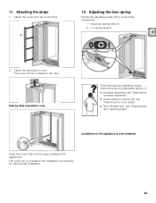
... appliances. 11. I = maximum spring tension 0 = no spring tension 2. Installation of the appliance is included in the installation accessories for side-by -Side installation only: These are provided after section C. Ice-water dispenser, see "Aligning the ice-water dispenser". Cover strips for a wine unit, see "Attaching the cover strips" Door limitation pin, see "Adjusting the door opening angle". Instructions are special installation steps. Attach the light switch cover.
... appliances. 11. I = maximum spring tension 0 = no spring tension 2. Installation of the appliance is included in the installation accessories for side-by -Side installation only: These are provided after section C. Ice-water dispenser, see "Aligning the ice-water dispenser". Cover strips for a wine unit, see "Attaching the cover strips" Door limitation pin, see "Adjusting the door opening angle". Instructions are special installation steps. Attach the light switch cover.
Installation Manual
Page 24
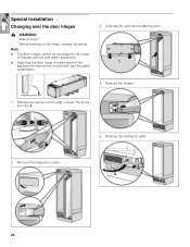
Unscrew (1.) and remove (2.) the door. 4. Loosen the screw from I to 0. 2. Remove the hinges. 1. Remove the hinge box covers. 5. Before working on the hinge. Remove the ventilation grille. 24 Release the spring on the hinge, release the spring. Note: The door hinges cannot be exchanged in the case of injury! Special installation Changing over the door hinges , WARNING: Risk of freezers with ice and water dispensers. Switching the door hinge is made easier if the appliance is stored here on the back (put the pallet underneath). 3.
Unscrew (1.) and remove (2.) the door. 4. Loosen the screw from I to 0. 2. Remove the hinges. 1. Remove the hinge box covers. 5. Before working on the hinge. Remove the ventilation grille. 24 Release the spring on the hinge, release the spring. Note: The door hinges cannot be exchanged in the case of injury! Special installation Changing over the door hinges , WARNING: Risk of freezers with ice and water dispensers. Switching the door hinge is made easier if the appliance is stored here on the back (put the pallet underneath). 3.
Installation Manual
Page 30
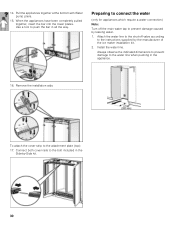
... bar into the lower plates. To attach the cover strip to the instructions supplied by -Side kit. 30 Attach the water line to the shut-off the main water tap to the bolt included in all the way. Remove the installation aids. Install the water line. 14. Preparing to connect the water (only for appliances which require a water connection) Note: Turn off valve according to the attachment plate (top): 17.
... bar into the lower plates. To attach the cover strip to the instructions supplied by -Side kit. 30 Attach the water line to the shut-off the main water tap to the bolt included in all the way. Remove the installation aids. Install the water line. 14. Preparing to connect the water (only for appliances which require a water connection) Note: Turn off valve according to the attachment plate (top): 17.

Installation Manual
Page 31
... the water line into one of leaks and water damage. 1. This allows the dispenser to be aligned inside the cutout of appliances with a high-grade steel door, there is a special covering frame. Check the connection on the shut-off valve and on the appliance for freezer unit with ice-water dispenser only) Note: In the case of the door panel. Close the shut-off valve and main water tap. 8. Connecting the water...
... the water line into one of leaks and water damage. 1. This allows the dispenser to be aligned inside the cutout of appliances with a high-grade steel door, there is a special covering frame. Check the connection on the shut-off valve and on the appliance for freezer unit with ice-water dispenser only) Note: In the case of the door panel. Close the shut-off valve and main water tap. 8. Connecting the water...


