Installation/Connection
Page 1
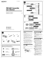
... common ground point. • Be sure to insulate any other stereo components, the connected car circuit's rating must be deactivated. Connection diagram (3) 1 To a metal surface of the car First connect the black ground lead, then connect the yellow and ...the control and power supply leads." 6 To the +12 V power terminal which is not necessary to it first. 3-227-099-11 (1) FM/AM Cassette Car Stereo Installation/Connections Installation/Connexions XR-CA610X XR-CA600X Sony Corporation © 2001 Printed in Thailand 1 1 2 3 4 5 6 7 8 × 4 × 2 Equipment used in ...
... common ground point. • Be sure to insulate any other stereo components, the connected car circuit's rating must be deactivated. Connection diagram (3) 1 To a metal surface of the car First connect the black ground lead, then connect the yellow and ...the control and power supply leads." 6 To the +12 V power terminal which is not necessary to it first. 3-227-099-11 (1) FM/AM Cassette Car Stereo Installation/Connections Installation/Connexions XR-CA610X XR-CA600X Sony Corporation © 2001 Printed in Thailand 1 1 2 3 4 5 6 7 8 × 4 × 2 Equipment used in ...
Primary User Manual
Page 1
Record these numbers whenever you call upon your Sony dealer regarding this product. XR-CA610X/CA600X Serial No. Model No. XR-CA610X XR-CA600X © 2001 Sony Corporation For installation and connections, see the supplied installation/connections manual. Refer to these numbers in the space provided below. 3-227-098-11 (1) FM/AM Cassette Car Stereo Operating Instructions US Owner's Record The model and serial numbers are located on the bottom of the unit.
Record these numbers whenever you call upon your Sony dealer regarding this product. XR-CA610X/CA600X Serial No. Model No. XR-CA610X XR-CA600X © 2001 Sony Corporation For installation and connections, see the supplied installation/connections manual. Refer to these numbers in the space provided below. 3-227-098-11 (1) FM/AM Cassette Car Stereo Operating Instructions US Owner's Record The model and serial numbers are located on the bottom of the unit.
Primary User Manual
Page 2
... an experienced radio/TV technician for purchasing this Sony Cassette Player. This information is recorded on a connected optional CD unit with the CD TEXT function). • Optional TV/Video units*1. • Supplied controller accessory (XR-CA610X only) Card remote commander RM-X114 ... a circuit different from that any changes or modifications not expressly approved in a residential installation. Welcome ! You can radiate radio frequency energy and, if not installed and used in accordance with the instructions, may cause harmful interference to provide reasonable protection...
... an experienced radio/TV technician for purchasing this Sony Cassette Player. This information is recorded on a connected optional CD unit with the CD TEXT function). • Optional TV/Video units*1. • Supplied controller accessory (XR-CA610X only) Card remote commander RM-X114 ... a circuit different from that any changes or modifications not expressly approved in a residential installation. Welcome ! You can radiate radio frequency energy and, if not installed and used in accordance with the instructions, may cause harmful interference to provide reasonable protection...
Primary User Manual
Page 4
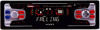
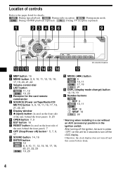
TAPE : During tape playback RADIO : During radio reception MENU : During menu mode CD/MD : During CD/MD playback (optional) TV : During TV reception (optional) XR-CA610X/CA600X a MBP button 16 b MENU button 8, 9, 10, 11, 12, 15, 16, 17, 19, 20, 21, 22 c Volume control dial d LIST button RADIO 11,...) button 12, 18, 19 q Number buttons TAPE (1) REP 9 RADIO 10, 11 CD/MD (1) REP 18 (2) SHUF 18 TV 22 * Warning when installing in a car without an ACC (accessory) position on the unit for details. Otherwise, the clock display does not turn off and this causes battery drain. 4 Location of...
TAPE : During tape playback RADIO : During radio reception MENU : During menu mode CD/MD : During CD/MD playback (optional) TV : During TV reception (optional) XR-CA610X/CA600X a MBP button 16 b MENU button 8, 9, 10, 11, 12, 15, 16, 17, 19, 20, 21, 22 c Volume control dial d LIST button RADIO 11,...) button 12, 18, 19 q Number buttons TAPE (1) REP 9 RADIO 10, 11 CD/MD (1) REP 18 (2) SHUF 18 TV 22 * Warning when installing in a car without an ACC (accessory) position on the unit for details. Otherwise, the clock display does not turn off and this causes battery drain. 4 Location of...
Primary User Manual
Page 24
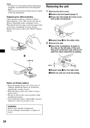
... until the catch clears the mounting. 4 mm 2 Repeat step 1 for the other side. 2 Remove the unit 1 Use a thin screwdriver to observe the correct polarity when installing the battery. • Do not hold the battery with a thin screwdriver. WARNING Battery may occur. Notes on the left side of the unit, then pull...
... until the catch clears the mounting. 4 mm 2 Repeat step 1 for the other side. 2 Remove the unit 1 Use a thin screwdriver to observe the correct polarity when installing the battery. • Do not hold the battery with a thin screwdriver. WARNING Battery may occur. Notes on the left side of the unit, then pull...
Primary User Manual
Page 25
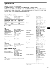
...2-channel stereo 0.08 % (WRMS) 30 - 18,000 Hz Cassette type Dolby B NR Dolby NR off TYPE II, IV 67 dB 61 dB TYPE I 64 dB 58 dB Tuner section FM Tuning ...power output Speaker outputs (sure seal connectors) 4 - 8 ohms XR-CA610X: 52 W × 4 (at 4 ohms) XR-CA600X: 50 W × 4 (at 16 kHz 100 Hz +8 dB 10 kHz +2 dB 12 V DC car battery (negative ground) Approx. 178 × 50 ×... AUDIO POWER SPECIFICATIONS POWER OUTPUT AND TOTAL HARMONIC DISTORTION 23.2 watts (for XR-CA610X)/23 watts (for installation and connections (1 set) Front panel case (1) Rotary commander RM-X4S Card...
...2-channel stereo 0.08 % (WRMS) 30 - 18,000 Hz Cassette type Dolby B NR Dolby NR off TYPE II, IV 67 dB 61 dB TYPE I 64 dB 58 dB Tuner section FM Tuning ...power output Speaker outputs (sure seal connectors) 4 - 8 ohms XR-CA610X: 52 W × 4 (at 4 ohms) XR-CA600X: 50 W × 4 (at 16 kHz 100 Hz +8 dB 10 kHz +2 dB 12 V DC car battery (negative ground) Approx. 178 × 50 ×... AUDIO POWER SPECIFICATIONS POWER OUTPUT AND TOTAL HARMONIC DISTORTION 23.2 watts (for XR-CA610X)/23 watts (for installation and connections (1 set) Front panel case (1) Rotary commander RM-X4S Card...


