Installation/Connection
Page 1
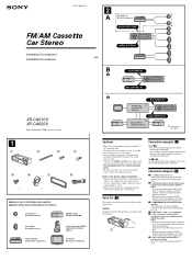
Connection diagram (3) 1 To a metal surface of the car First connect the black ground lead, then connect the yellow and red power input leads. 2 To the power antenna control lead or... amplifier This connection is only for negative ground 12 V DC operation only. • Do not get the wires under a screw, or caught in moving parts (e.g. 3-227-099-11 (1) FM/AM Cassette Car Stereo Installation/Connections Installation/Connexions XR-CA610X XR-CA600X Sony Corporation © 2001 Printed in Thailand 1 1 2 3 4 5 6 7 8 × 4 × 2 Equipment used in illustrations (not supplied...
Connection diagram (3) 1 To a metal surface of the car First connect the black ground lead, then connect the yellow and red power input leads. 2 To the power antenna control lead or... amplifier This connection is only for negative ground 12 V DC operation only. • Do not get the wires under a screw, or caught in moving parts (e.g. 3-227-099-11 (1) FM/AM Cassette Car Stereo Installation/Connections Installation/Connexions XR-CA610X XR-CA600X Sony Corporation © 2001 Printed in Thailand 1 1 2 3 4 5 6 7 8 × 4 × 2 Equipment used in illustrations (not supplied...


