Hookup Diagram
Page 1
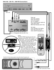
... the green wire connects to a parking brake ground trigger, and the parking brake is set Video RCA Cable RM-X120 Remote (DVX-100) Not Used DVX-100 RM-X130 Display DVX-100 remote IR eye DVX-100 RF modulator box Notes The XAV-7W IR remote eye acts as a receiver for the DVX-...100's remote (RM-X120). When using the DVX-100 with the XAV-7W) Parts List XAV-7W complete DVX-100 Changer XA-118 Adapter RC-91 UniLink/RCA cable set . No other head unit, the supplied IR remote eye must be used . XAV-7W Connections XAV-7W ...
... the green wire connects to a parking brake ground trigger, and the parking brake is set Video RCA Cable RM-X120 Remote (DVX-100) Not Used DVX-100 RM-X130 Display DVX-100 remote IR eye DVX-100 RF modulator box Notes The XAV-7W IR remote eye acts as a receiver for the DVX-...100's remote (RM-X120). When using the DVX-100 with the XAV-7W) Parts List XAV-7W complete DVX-100 Changer XA-118 Adapter RC-91 UniLink/RCA cable set . No other head unit, the supplied IR remote eye must be used . XAV-7W Connections XAV-7W ...

Installation Instructions
Page 3
Table of Contents Precautions ...2 Parts List ...4 1 Installing the Main Unit 5 Before installation ...5 Installation procedure ...7 Installing the connection box XA-114 9 Hooking up the connection box 9 2 Main Unit Connections 10 Connection Example 11 Connecting Information 13 Using the tap ...13 Connecting the parking cord 13 3 Car Systems Connections 14 4 After Installation and Connections 16 Removing the Front Panel Plate 17 3
Table of Contents Precautions ...2 Parts List ...4 1 Installing the Main Unit 5 Before installation ...5 Installation procedure ...7 Installing the connection box XA-114 9 Hooking up the connection box 9 2 Main Unit Connections 10 Connection Example 11 Connecting Information 13 Using the tap ...13 Connecting the parking cord 13 3 Car Systems Connections 14 4 After Installation and Connections 16 Removing the Front Panel Plate 17 3
Installation Instructions
Page 5
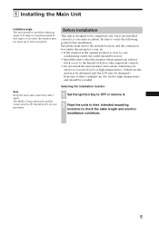
The Media Center main unit and the connection box 1 should not be in their intended mounting locations to check the cable... 1 Set the ignition key to a air- Install the main unit to the in-dash location, and the connection box under the navigator's seat, etc. • If the monitor in the opened up will not block access to...that the monitor when opened position is designed to verify the following points before installation. Note Keep the units and connection cables apart. 1 Installing the Main Unit Installation angle The unit should be completely safe, but if not installed correctly...
The Media Center main unit and the connection box 1 should not be in their intended mounting locations to check the cable... 1 Set the ignition key to a air- Install the main unit to the in-dash location, and the connection box under the navigator's seat, etc. • If the monitor in the opened up will not block access to...that the monitor when opened position is designed to verify the following points before installation. Note Keep the units and connection cables apart. 1 Installing the Main Unit Installation angle The unit should be completely safe, but if not installed correctly...
Installation Instructions
Page 9
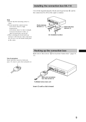
...heard. 9 Use of hook-and-loop fastener 8 and fix the connection box 1 on the carpet or similar. Hook-and-loop fastener 8 Hook-and-loop fastener 8 On installation surface Hooking up the connection box Refer also to high temperatures - To remove, press here and pull...to the section "3 Car Systems Connections" (page 14 15). in the center. Installing the connection box XA-114 Cut off the required length of connectors Insert until a click is clean. • Do not install the connection box - Main unit/connection box interconnect 3 To Media Center main unit Insert 3 until ...
...heard. 9 Use of hook-and-loop fastener 8 and fix the connection box 1 on the carpet or similar. Hook-and-loop fastener 8 Hook-and-loop fastener 8 On installation surface Hooking up the connection box Refer also to high temperatures - To remove, press here and pull...to the section "3 Car Systems Connections" (page 14 15). in the center. Installing the connection box XA-114 Cut off the required length of connectors Insert until a click is clean. • Do not install the connection box - Main unit/connection box interconnect 3 To Media Center main unit Insert 3 until ...

Installation Instructions
Page 10
2 Main Unit Connections Use of connectors Insert until the connector clicks into place. Refer also to the section "3 Car Systems Connections" (page 14 - 15). To connection box Insert until a click is heard. 10 To remove, press here and pull out. Main unit/ connection box interconnect 3 Power supply leads 2 (for main unit) Insert 2 and 3 until the connector clicks into place. To remove, press here and pull out.
2 Main Unit Connections Use of connectors Insert until the connector clicks into place. Refer also to the section "3 Car Systems Connections" (page 14 - 15). To connection box Insert until a click is heard. 10 To remove, press here and pull out. Main unit/ connection box interconnect 3 Power supply leads 2 (for main unit) Insert 2 and 3 until the connector clicks into place. To remove, press here and pull out.
Installation Instructions
Page 12
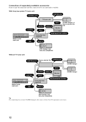
... unit TV tuner unit CONTROL OUTPUT VIDEO IN INPUT INPUT Monitor CD/MD changer, or Source selector XAC30 Connection box (supplied) REAR MONITOR OUTPUT XAV INPUT1/2 Without TV tuner unit DVD changer (not Sony bus compatible) Media Center main unit CONTROL(OUT) Source selector XAC30 CONTROL(IN) CD/MD changer INPUT CONTROL OUTPUT VIDEO IN INPUT...
... unit TV tuner unit CONTROL OUTPUT VIDEO IN INPUT INPUT Monitor CD/MD changer, or Source selector XAC30 Connection box (supplied) REAR MONITOR OUTPUT XAV INPUT1/2 Without TV tuner unit DVD changer (not Sony bus compatible) Media Center main unit CONTROL(OUT) Source selector XAC30 CONTROL(IN) CD/MD changer INPUT CONTROL OUTPUT VIDEO IN INPUT...
Installation Instructions
Page 14
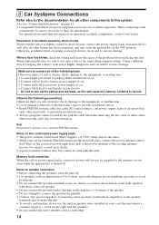
... to their documentation. Also see "Connecting Information" on car chassis. * Do not to mix up the yellow and red leads, as this unit. Observe the following leads. Notes on separately available components, contact your dealer. • A power antenna without relay box cannot be used with electrician's tape... a fuse has blown, check the wiring and locate the cause of the right speakers with the ignition key in parallel. • Connect only passive speakers. Otherwise there is highly dangerous and can lead to electric shock and to the memory circuit even when the ignition key...
... to their documentation. Also see "Connecting Information" on car chassis. * Do not to mix up the yellow and red leads, as this unit. Observe the following leads. Notes on separately available components, contact your dealer. • A power antenna without relay box cannot be used with electrician's tape... a fuse has blown, check the wiring and locate the cause of the right speakers with the ignition key in parallel. • Connect only passive speakers. Otherwise there is highly dangerous and can lead to electric shock and to the memory circuit even when the ignition key...
Installation Instructions
Page 15
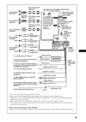
...control lead or power supply lead of car Tap 5 Light green (2 m) *1 Be sure to connect the black ground lead to connect this lead if there is no accessory position, connect to the +12 V power (battery) terminal which is energized at all times*1 To the +12...) Right RCA interconnects TV tuner unit XAV (optional) XT-63V (optional) White White/black Gray Gray/black Connection box 1 Main unit/ connection box interconnect 3 Rotary Commander RM-X4S (optional) Left Rear speakers (optional) Right Green Green/black Purple Purple/black Media Center main unit From car antenna To a...
...control lead or power supply lead of car Tap 5 Light green (2 m) *1 Be sure to connect the black ground lead to connect this lead if there is no accessory position, connect to the +12 V power (battery) terminal which is energized at all times*1 To the +12...) Right RCA interconnects TV tuner unit XAV (optional) XT-63V (optional) White White/black Gray Gray/black Connection box 1 Main unit/ connection box interconnect 3 Rotary Commander RM-X4S (optional) Left Rear speakers (optional) Right Green Green/black Purple Purple/black Media Center main unit From car antenna To a...
Operating Instructions (primary manual)
Page 11
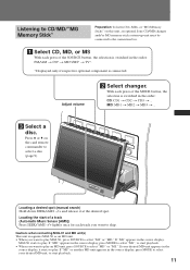
... you want to play MGS-X1, press SOURCE to select "MS" or "MD." Press V or v on this unit, an optional Sony CD/MD changer and/or MG memory stick system-up unit must be connected to the connection box. 1 Select CD, MD, or MS With each press of the MODE button, the selection is... connected. If your desired MD unit, to start of a track (Automatic Music Sensor [AMS]) Press SEEK/AMS -/+ lightly once for each track...
... you want to play MGS-X1, press SOURCE to select "MS" or "MD." Press V or v on this unit, an optional Sony CD/MD changer and/or MG memory stick system-up unit must be connected to the connection box. 1 Select CD, MD, or MS With each press of the MODE button, the selection is... connected. If your desired MD unit, to start of a track (Automatic Music Sensor [AMS]) Press SEEK/AMS -/+ lightly once for each track...
Operating Instructions (primary manual)
Page 12
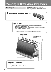
... view TV programs on this unit, an optional Sony TV tuner unit XT-63V must be connected to the connection box. 1 Open up /Close the monitor ATT CLOOPSEEN/ ANGLE 3 Select a channel. DISC VOL . SEEK > SOURCE MODE OFF ATT OCLPOESNE/ 2 Select TV. Using auto tuning Press SEEK/AMS -/+ lightly until the desired channel is received. 12
... view TV programs on this unit, an optional Sony TV tuner unit XT-63V must be connected to the connection box. 1 Open up /Close the monitor ATT CLOOPSEEN/ ANGLE 3 Select a channel. DISC VOL . SEEK > SOURCE MODE OFF ATT OCLPOESNE/ 2 Select TV. Using auto tuning Press SEEK/AMS -/+ lightly until the desired channel is received. 12

Operating Instructions (primary manual)
Page 13
SEEK > SOURCE MODE ATT CLOOPSEEN/ ANGLE 13 VOL . Pressing MODE when "TV" is selected switches the selection in the order: TV1* t TV2* t VIDEO1 t VIDEO2. * Displayed only if respective optional component is switched in the order: FM1 t CD* t MD*/MS* t TV*. SEEK > SOURCE MODE OFF ATT OCLPOESNE/ 2 Select VIDEO1 or VIDEO2. With each press of SOURCE, the selection is connected. Watching other video components Preparation: To view DVDs on this unit, an optional Sony DVD changer system must be connected to the connection box. 1 Open up the monitor (page 6). DISC VOL .
SEEK > SOURCE MODE ATT CLOOPSEEN/ ANGLE 13 VOL . Pressing MODE when "TV" is selected switches the selection in the order: TV1* t TV2* t VIDEO1 t VIDEO2. * Displayed only if respective optional component is switched in the order: FM1 t CD* t MD*/MS* t TV*. SEEK > SOURCE MODE OFF ATT OCLPOESNE/ 2 Select VIDEO1 or VIDEO2. With each press of SOURCE, the selection is connected. Watching other video components Preparation: To view DVDs on this unit, an optional Sony DVD changer system must be connected to the connection box. 1 Open up the monitor (page 6). DISC VOL .

Operating Instructions (primary manual)
Page 23
CD/MD/"MG Memory Stick" Playback Preparation: To listen CDs, MDs, or "MG Memory Sticks" on this unit, an optional Sony CD/MD changer and/or MG memory stick system-up a list of a CD TEXT disc or an album. 1 Source type and changer number 2 Disc number 3 ... an MP3 file is displayed only when an optional MD unit with very many characters, information may not be connected to the connection box. Or information may not scroll. Pressing LIST on the card remote commander brings up unit must be displayed. • This unit cannot display the artist ...
CD/MD/"MG Memory Stick" Playback Preparation: To listen CDs, MDs, or "MG Memory Sticks" on this unit, an optional Sony CD/MD changer and/or MG memory stick system-up a list of a CD TEXT disc or an album. 1 Source type and changer number 2 Disc number 3 ... an MP3 file is displayed only when an optional MD unit with very many characters, information may not be connected to the connection box. Or information may not scroll. Pressing LIST on the card remote commander brings up unit must be displayed. • This unit cannot display the artist ...
Operating Instructions (primary manual)
Page 30
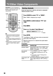
... regular display appears again. Assign name to a TV station Proceed steps described in step 1.) 30 MENU 2 B/b Press MODE to a station" (page 20). (Receive "TV1" or "TV2" in "Assigning a name to switch between "TV1" and "TV2". 3 Proceed steps 3 and 4 of their frequency. TV operation Selection...TV1" or "TV2". Store a channel manually 1 Press SOURCE to select "TV" or "VIDEO". 2 Press MODE to the connection box. TV/Other Video Components Preparation: To view TV programs on this unit, an optional Sony TV tuner unit XT-63V must be connected to switch between "TV1" and V/v "TV2".
... regular display appears again. Assign name to a TV station Proceed steps described in step 1.) 30 MENU 2 B/b Press MODE to a station" (page 20). (Receive "TV1" or "TV2" in "Assigning a name to switch between "TV1" and "TV2". 3 Proceed steps 3 and 4 of their frequency. TV operation Selection...TV1" or "TV2". Store a channel manually 1 Press SOURCE to select "TV" or "VIDEO". 2 Press MODE to the connection box. TV/Other Video Components Preparation: To view TV programs on this unit, an optional Sony TV tuner unit XT-63V must be connected to switch between "TV1" and V/v "TV2".

Operating Instructions (primary manual)
Page 38
...l 3 Press ENTER. Aux Sound Leve l 1dB 5 Press ENTER. ENTER Adjusting the output level 1 Press MENU. Adjusted sound level of the connected component. Note If the indication "VIDEO1" or "VIDEO2" does not appear when pressing SOURCE, see "Sound and display settings" (page 39) and...Note External components' sound output may be adjusted. Sound Settings MENU Setting the sound level for connected AUX components The sound output level of external video components, connecting INPUT1 and INPUT2 of the supplied connection box, can be too loud for another. 4 Press V or v to select a setting that...
...l 3 Press ENTER. Aux Sound Leve l 1dB 5 Press ENTER. ENTER Adjusting the output level 1 Press MENU. Adjusted sound level of the connected component. Note If the indication "VIDEO1" or "VIDEO2" does not appear when pressing SOURCE, see "Sound and display settings" (page 39) and...Note External components' sound output may be adjusted. Sound Settings MENU Setting the sound level for connected AUX components The sound output level of external video components, connecting INPUT1 and INPUT2 of the supplied connection box, can be too loud for another. 4 Press V or v to select a setting that...
Operating Instructions (primary manual)
Page 39
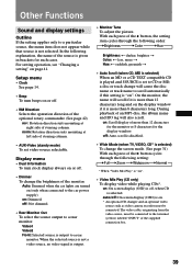
...or 8 characters for such cases. The video cable, originating from the video source, must be connected to scroll automatically if this setting is set video source selectable. Setup menu • Clock See ...through the following setting: Full Zoom Widezoom Normal * When "Video Mix Play" is "on (only when connected to a particular source, the menu item does not appear while that source is output. • Monitor...a disc or track change the brightness of the supplied connection box. 39 Other Functions Sound and display settings Outline If the setting applies only to the car power ...
...or 8 characters for such cases. The video cable, originating from the video source, must be connected to scroll automatically if this setting is set video source selectable. Setup menu • Clock See ...through the following setting: Full Zoom Widezoom Normal * When "Video Mix Play" is "on (only when connected to a particular source, the menu item does not appear while that source is output. • Monitor...a disc or track change the brightness of the supplied connection box. 39 Other Functions Sound and display settings Outline If the setting applies only to the car power ...
Operating Instructions (primary manual)
Page 42
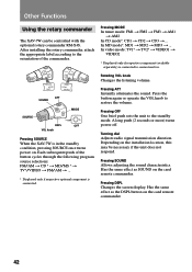
In MD mode*: MD1 t MD2 t MD3 t ... Pressing OFF One brief push sets the unit to connection box. Turning dial Adjusts radio signal transmission direction. Pressing MODE In tuner mode: FM1 t FM2 t FM3 t AM1 t AM2 In CD mode*: CD1 t CD2 t CD3 t ... Depending on... commander. 42 Has the same effect as SOUND on . A long push (2 seconds or more) turns power off. Other Functions Using the rotary commander The XAV-7W can be necessary if the unit does not respond. After installing the rotary commander, attach the appropriate label according to restore the volume. Has the...
In MD mode*: MD1 t MD2 t MD3 t ... Pressing OFF One brief push sets the unit to connection box. Turning dial Adjusts radio signal transmission direction. Pressing MODE In tuner mode: FM1 t FM2 t FM3 t AM1 t AM2 In CD mode*: CD1 t CD2 t CD3 t ... Depending on... commander. 42 Has the same effect as SOUND on . A long push (2 seconds or more) turns power off. Other Functions Using the rotary commander The XAV-7W can be necessary if the unit does not respond. After installing the rotary commander, attach the appropriate label according to restore the volume. Has the...
Operating Instructions (primary manual)
Page 47
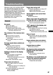
...is shorting on ". , An optional power amplifier is not connected correctly. , Check the connection. Stored stations and correct time are not matched correctly with electrical tape to be defective. Controls have a relay box. Power does not go off by pressing OFF for more ... , Press OFF on . , Power supply wiring is connected and you connect the optional equipment. , The cord has been disconnected. Connect the cord securely. 47 In such a case, contact the Technical Information Center, your dealer, or the nearest Sony service center. "ATT" appears in amplifier. No picture, or no ...
...is shorting on ". , An optional power amplifier is not connected correctly. , Check the connection. Stored stations and correct time are not matched correctly with electrical tape to be defective. Controls have a relay box. Power does not go off by pressing OFF for more ... , Press OFF on . , Power supply wiring is connected and you connect the optional equipment. , The cord has been disconnected. Connect the cord securely. 47 In such a case, contact the Technical Information Center, your dealer, or the nearest Sony service center. "ATT" appears in amplifier. No picture, or no ...
Operating Instructions (primary manual)
Page 48
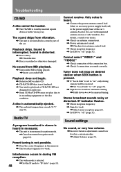
..., The unit is in a certain speaker. , Adjust balance (page 35). A disc is interrupted. For details, consult your dealer. , Check car antenna connections. , Power antenna not raised. , Check power antenna control lead. , Check reception frequency. , Set DSO to "off " (page 32). Sound settings ... 48 Playback skips. Preset tuning is not possible. , Store the correct frequency in a sturdy part of the connection box. , Check if connections are made correctly. Troubleshooting CD/MD A disc cannot be received. , Set "Local Seek" to "off" (page 25). , Signal is too weak for automatic tuning. ,...
..., The unit is in a certain speaker. , Adjust balance (page 35). A disc is interrupted. For details, consult your dealer. , Check car antenna connections. , Power antenna not raised. , Check power antenna control lead. , Check reception frequency. , Set DSO to "off " (page 32). Sound settings ... 48 Playback skips. Preset tuning is not possible. , Store the correct frequency in a sturdy part of the connection box. , Check if connections are made correctly. Troubleshooting CD/MD A disc cannot be received. , Set "Local Seek" to "off" (page 25). , Signal is too weak for automatic tuning. ,...
Operating Instructions (primary manual)
Page 50
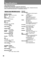
Media center/FM/AM receiver Monitor section Display type Wide LCD color monitor Size 7 in .) (W × H × D) Mass Approx. 1.7 kg (3 lb 12 oz) Supplied accessories Card remote commander RM-X118 (1) (incl. 1 lithium battery) Connection box (1) Parts for installation and connections (1 set) Operating Instructions (1 set) Optional accessories TV tuner unit XT-63V Rotary commander RM-X4S 50 Specifications...
Media center/FM/AM receiver Monitor section Display type Wide LCD color monitor Size 7 in .) (W × H × D) Mass Approx. 1.7 kg (3 lb 12 oz) Supplied accessories Card remote commander RM-X118 (1) (incl. 1 lithium battery) Connection box (1) Parts for installation and connections (1 set) Operating Instructions (1 set) Optional accessories TV tuner unit XT-63V Rotary commander RM-X4S 50 Specifications...
Operating Instructions (primary manual)
Page 51
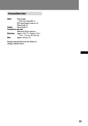
Connection box Inputs Video/audio (Sony bus compatible, 1) BUS control input connector (1) Video/audio (2) Outputs Video/audio (1) Connection to main unit Dimensions Dedicated 22-pin connector Approx. 136 × 77 × 30 mm (5 3/8 × 3 1/8 × 1 3/16 in.) (W × H × D) Mass Approx. 260 g (9 oz) Design and specifications are subject to change without notice. 51
Connection box Inputs Video/audio (Sony bus compatible, 1) BUS control input connector (1) Video/audio (2) Outputs Video/audio (1) Connection to main unit Dimensions Dedicated 22-pin connector Approx. 136 × 77 × 30 mm (5 3/8 × 3 1/8 × 1 3/16 in.) (W × H × D) Mass Approx. 260 g (9 oz) Design and specifications are subject to change without notice. 51


