
Operating Instructions
Page 1
4-156-596-11(1) Video Projector Operating Instructions VPL-HW15 © 2009 Sony Corporation
4-156-596-11(1) Video Projector Operating Instructions VPL-HW15 © 2009 Sony Corporation

Operating Instructions
Page 4
... 8 Remote Control 9 Connections and Preparations Unpacking 10 Step 1: Installing the Projector ......... 11 Before Setting Up the Projector 11 Positioning the Projector and a screen 13 Step 2: Adjusting the Picture Position 17 Step 3: Connecting the Projector ..... 22 Connecting to a VCR 22 Connecting to a Computer ......... 25 ...the Screen 28 Turning Off the Power 29 Operating the BRAVIA Sync Compatible Equipment with the Remote Control of the Projector ......30 Selecting the Wide Screen Mode .....32 Selecting the Picture Viewing Mode 34 Adjusting the Picture Quality ...........35 ...
... 8 Remote Control 9 Connections and Preparations Unpacking 10 Step 1: Installing the Projector ......... 11 Before Setting Up the Projector 11 Positioning the Projector and a screen 13 Step 2: Adjusting the Picture Position 17 Step 3: Connecting the Projector ..... 22 Connecting to a VCR 22 Connecting to a Computer ......... 25 ...the Screen 28 Turning Off the Power 29 Operating the BRAVIA Sync Compatible Equipment with the Remote Control of the Projector ......30 Selecting the Wide Screen Mode .....32 Selecting the Picture Viewing Mode 34 Adjusting the Picture Quality ...........35 ...
Operating Instructions
Page 5
... LLC. It also supports HDCP. 5 HDMI, the HDMI logo and High-Definition Multimedia Interface are trademarks or registered trademarks of Sony Computer Entertainment Inc. Others About the Control for HDMI is an HDMI standard mutual control function which uses the HDMI CEC (Consumer... Electronics Control) specification. This projector supports DeepColor, x.v.Color, LipSync and computer input signal of HDMI standards. Control for HDMI ...........58 About the x.v.Color 59 Troubleshooting...
... LLC. It also supports HDCP. 5 HDMI, the HDMI logo and High-Definition Multimedia Interface are trademarks or registered trademarks of Sony Computer Entertainment Inc. Others About the Control for HDMI is an HDMI standard mutual control function which uses the HDMI CEC (Consumer... Electronics Control) specification. This projector supports DeepColor, x.v.Color, LipSync and computer input signal of HDMI standards. Control for HDMI ...........58 About the x.v.Color 59 Troubleshooting...

Operating Instructions
Page 6
Caution The projector is hot. they will come in handy if you turn off the power with the I/1 (ON/STANDBY) switch, do not disconnect the unit from the ... wall outlet, even if the unit itself has been turned off. • Do not look into the cabinet, unplug the unit and have to the projector. For maximum protection, repack your unit as it is connected to be used for several days. • To disconnect the cord, pull it was originally...
Caution The projector is hot. they will come in handy if you turn off the power with the I/1 (ON/STANDBY) switch, do not disconnect the unit from the ... wall outlet, even if the unit itself has been turned off. • Do not look into the cabinet, unplug the unit and have to the projector. For maximum protection, repack your unit as it is connected to be used for several days. • To disconnect the cord, pull it was originally...

Operating Instructions
Page 7
Location of Controls Location of Controls Front/Right Side You can use the buttons on the control panel with the same names as those on the remote control to operate the projector. Control panel Lens shift dials (1 page 18) M/m/
Location of Controls Location of Controls Front/Right Side You can use the buttons on the control panel with the same names as those on the remote control to operate the projector. Control panel Lens shift dials (1 page 18) M/m/

Operating Instructions
Page 8
Rear/Bottom Ventilation holes (intake) (1 page 12) Ventilation holes (intake) (1 page 12) Ventilation holes (intake) (1 page 12) Ventilation holes (intake) (1 page 12) Lamp cover (1 page 66) Adjusters (1 page 21) Filter holder (1 page 67) Ventilation holes (intake) (1 page 12) Projector suspension support attaching hole (1 page 77) 8
Rear/Bottom Ventilation holes (intake) (1 page 12) Ventilation holes (intake) (1 page 12) Ventilation holes (intake) (1 page 12) Ventilation holes (intake) (1 page 12) Lamp cover (1 page 66) Adjusters (1 page 21) Filter holder (1 page 67) Ventilation holes (intake) (1 page 12) Projector suspension support attaching hole (1 page 77) 8

Operating Instructions
Page 10
... generate heat. To avoid risk of explosion if battery is put onto the lens. Connections and Preparations This section describes how to install the projector and screen, how to connect the equipment from which you want to open. Remove this lens cap when you use size AA (R6) ...manganese or alkaline batteries. Push and slide to project the picture, etc. CAUTION Danger of explosion, use the projector. • Operating Instructions (this manual) Inserting the batteries into the remote control Insert the batteries E side first as shown in the relative area or...
... generate heat. To avoid risk of explosion if battery is put onto the lens. Connections and Preparations This section describes how to install the projector and screen, how to connect the equipment from which you want to open. Remove this lens cap when you use size AA (R6) ...manganese or alkaline batteries. Push and slide to project the picture, etc. CAUTION Danger of explosion, use the projector. • Operating Instructions (this manual) Inserting the batteries into the remote control Insert the batteries E side first as shown in the relative area or...

Operating Instructions
Page 11
... 7/8 inches) 30 cm (11 7/8 inches) 30 cm (11 7/8 inches) 11 Near a heat or smoke sensor Unsuitable installation Do not place the projector in temperature. Poorly ventilated location Malfunction of the sensor may cause malfunction or damage to have broader options for placing the... projector and viewing pictures easily. The lens shift allows you to the projector. Very dusty and extremely smoky locations Leave space of more than 30 cm (11 7/8 inches) around...
... 7/8 inches) 30 cm (11 7/8 inches) 30 cm (11 7/8 inches) 11 Near a heat or smoke sensor Unsuitable installation Do not place the projector in temperature. Poorly ventilated location Malfunction of the sensor may cause malfunction or damage to have broader options for placing the... projector and viewing pictures easily. The lens shift allows you to the projector. Very dusty and extremely smoky locations Leave space of more than 30 cm (11 7/8 inches) around...
Operating Instructions
Page 12
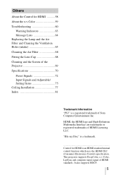
...than 15 degrees. Blocking the ventilation holes (intake or exhaust) Ventilation holes (intake) Ventilation holes (exhaust) Tip For details on the ceiling. Installing the projector in such a location may result in the Setup menu to "High" (1 page 50). Improper use Do not do any of the following while using... the projector at high altitudes could have adverse effects, such as reducing the reliability of certain components. 15° or more 15° or more 15&#...
...than 15 degrees. Blocking the ventilation holes (intake or exhaust) Ventilation holes (intake) Ventilation holes (exhaust) Tip For details on the ceiling. Installing the projector in such a location may result in the Setup menu to "High" (1 page 50). Improper use Do not do any of the following while using... the projector at high altitudes could have adverse effects, such as reducing the reliability of certain components. 15° or more 15° or more 15&#...

Operating Instructions
Page 13
.... x: Horizontal distance between the center of the screen and the center of the projector and screen. Use the values L, x and y in the illustration. For installation of the projector's lens. Screen * ** * Installation position not using lens shift (x = 0, y = 0) ** Example of installation position using lens shift... quality picture if you use the lens shift features. 1 Determine the installation position of the projector's lens. y: Vertical distance between the screen and the front end of the projector on a ceiling, see "Step 2: Adjusting the Picture Position." (1 page 17) 13
.... x: Horizontal distance between the center of the screen and the center of the projector and screen. Use the values L, x and y in the illustration. For installation of the projector's lens. Screen * ** * Installation position not using lens shift (x = 0, y = 0) ** Example of installation position using lens shift... quality picture if you use the lens shift features. 1 Determine the installation position of the projector's lens. y: Vertical distance between the screen and the front end of the projector on a ceiling, see "Step 2: Adjusting the Picture Position." (1 page 17) 13

Operating Instructions
Page 16
2 Position the projector so that it fits the screen. (1 page 17) Note When using a screen with an uneven surface, stripes pattern may rarely appear on the screen depending on the screen and adjust the picture so that the lens is not a malfunction of the projector. 16 Top view Screen 3 Project an image on the distance between the screen and the projector or the zooming magnifications. This is parallel to the screen.
2 Position the projector so that it fits the screen. (1 page 17) Note When using a screen with an uneven surface, stripes pattern may rarely appear on the screen depending on the screen and adjust the picture so that the lens is not a malfunction of the projector. 16 Top view Screen 3 Project an image on the distance between the screen and the projector or the zooming magnifications. This is parallel to the screen.

Operating Instructions
Page 17
Connections and Preparations Step 2: Adjusting the Picture Position Project an image on the screen and then adjust the picture position. 1 ON/STANDBY indicator 4 Lens shift dials Remote control detector 5, 6 Zoom lever, Focus ring 2 ?/1 (On/ standby) switch 3 LENS button Tip The ?/1 (ON/STANDBY), INPUT, MENU, and M/m/
Connections and Preparations Step 2: Adjusting the Picture Position Project an image on the screen and then adjust the picture position. 1 ON/STANDBY indicator 4 Lens shift dials Remote control detector 5, 6 Zoom lever, Focus ring 2 ?/1 (On/ standby) switch 3 LENS button Tip The ?/1 (ON/STANDBY), INPUT, MENU, and M/m/

Operating Instructions
Page 18
... displayed for 1 minute. Press the LENS button on the remote control to turn on the screen. 3 Display a test signal for performing adjustments. appears on the projector. The ON/STANDBY indicator flashes in green, and then lights in green. 2 Press the ?/1 (ON/STANDBY) switch to display the test signal. Flashes in green...
... displayed for 1 minute. Press the LENS button on the remote control to turn on the screen. 3 Display a test signal for performing adjustments. appears on the projector. The ON/STANDBY indicator flashes in green, and then lights in green. 2 Press the ?/1 (ON/STANDBY) switch to display the test signal. Flashes in green...

Operating Instructions
Page 20
... adjusted. In this connection, see the table on page 15 or 16. 5 Adjust the picture size using the focus ring. For details, see "Positioning the Projector and a screen" (1 page 13) as well. Zoom lever 6 Adjust the focus using the zoom lever. Range of movement of the projected picture Projected Picture H: Width...
... adjusted. In this connection, see the table on page 15 or 16. 5 Adjust the picture size using the focus ring. For details, see "Positioning the Projector and a screen" (1 page 13) as well. Zoom lever 6 Adjust the focus using the zoom lever. Range of movement of the projected picture Projected Picture H: Width...

Operating Instructions
Page 21
Connections and Preparations To adjust the tilt of a tilt will result in trapezoidal distortion in the projected image. • Be careful not to catch your finger when turning the adjusters. 21 Turn to keep the projector level. Adjusters Notes • Pointing the projector at too high or too low of the installation surface If the projector is installed on an uneven surface, use the adjusters to adjust.
Connections and Preparations To adjust the tilt of a tilt will result in trapezoidal distortion in the projected image. • Be careful not to catch your finger when turning the adjusters. 21 Turn to keep the projector level. Adjusters Notes • Pointing the projector at too high or too low of the installation surface If the projector is installed on an uneven surface, use the adjusters to adjust.

Operating Instructions
Page 22
...sure to pull it out from the plug, not the cable itself. • Refer to the operating instructions of the projector. Right side of the projector AV amplifier Speakers Equipment with the Control for HDMI compatible equipment, you can enjoy better picture quality by connecting a DVD player...the Function menu (1 page 52) and "About the Control for each connection. • Insert the cable plugs properly; Step 3: Connecting the Projector When making connections, be sure to do the following: • Turn off all equipment before making any connections. • Use the proper cables...
...sure to pull it out from the plug, not the cable itself. • Refer to the operating instructions of the projector. Right side of the projector AV amplifier Speakers Equipment with the Control for HDMI compatible equipment, you can enjoy better picture quality by connecting a DVD player...the Function menu (1 page 52) and "About the Control for each connection. • Insert the cable plugs properly; Step 3: Connecting the Projector When making connections, be sure to do the following: • Turn off all equipment before making any connections. • Use the proper cables...

Operating Instructions
Page 23
... Component video cable (not supplied) 23 Connections and Preparations Notes • When connecting an HDMI cable to the projector, make sure the V mark on the upper part of the HDMI input of the projector and the v mark on the connector of the cable is set at the same position. • If the... picture from equipment connected to equipment with component video output connectors Right side of the projector AV amplifier Speakers Equipment with an HDMI cable is not clear, check the settings of the connected equipment.
... Component video cable (not supplied) 23 Connections and Preparations Notes • When connecting an HDMI cable to the projector, make sure the V mark on the upper part of the HDMI input of the projector and the v mark on the connector of the cable is set at the same position. • If the... picture from equipment connected to equipment with component video output connectors Right side of the projector AV amplifier Speakers Equipment with an HDMI cable is not clear, check the settings of the connected equipment.

Operating Instructions
Page 24
... component video connectors. If the equipment to be connected has no S video connector, connect the cable to enjoy better picture quality. Right side of the projector Speakers AV amplifier Video equipment to S video or video output : Video signal flow S video or video cable (not supplied) Tip If you should connect the...
... component video connectors. If the equipment to be connected has no S video connector, connect the cable to enjoy better picture quality. Right side of the projector Speakers AV amplifier Video equipment to S video or video output : Video signal flow S video or video cable (not supplied) Tip If you should connect the...

Operating Instructions
Page 25
... pages 51, 64) Notes • When connecting an HDMI cable, make sure the V mark on the upper part of the HDMI input of the projector and the v mark on the connector of the cable is not clear, check the settings of the connected equipment. 25 Connections and Preparations Connecting to... a Computer Right side of the projector Computer to monitor output HD-Dsub15 pin cable (not supplied) or HDMI cable (not supplied) : Video signal flow When using an optional HDMI ...
... pages 51, 64) Notes • When connecting an HDMI cable, make sure the V mark on the upper part of the HDMI input of the projector and the v mark on the connector of the cable is not clear, check the settings of the connected equipment. 25 Connections and Preparations Connecting to... a Computer Right side of the projector Computer to monitor output HD-Dsub15 pin cable (not supplied) or HDMI cable (not supplied) : Video signal flow When using an optional HDMI ...

Operating Instructions
Page 28
...Picture on the Screen Example: To view the picture from the video equipment connected to the VIDEO INPUT connector. 1 Power on both the projector and the equipment connected to the projector. 2 Press INPUT to display the input palette on the screen. 3 Select the equipment from which to the...to the HDMI 1 connector Equipment connected to the HDMI 2 connector Press INPUT to suit your taste. Projecting This section describes how to operate the projector to view the picture from the equipment connected to project. When you want to HDMI 1 or HDMI 2 input of the picture to display Video ...
...Picture on the Screen Example: To view the picture from the video equipment connected to the VIDEO INPUT connector. 1 Power on both the projector and the equipment connected to the projector. 2 Press INPUT to display the input palette on the screen. 3 Select the equipment from which to the...to the HDMI 1 connector Equipment connected to the HDMI 2 connector Press INPUT to suit your taste. Projecting This section describes how to operate the projector to view the picture from the equipment connected to project. When you want to HDMI 1 or HDMI 2 input of the picture to display Video ...


