
Operating Instructions
Page 2
... shock, refer servicing to Part 15 of the FCC Rules. However, there is encouraged to try to radio or television reception, which the receiver is connected. - Connect the equipment into an outlet on a circuit different from that to which can radiate radio frequency energy and, if not installed and used in a particular...
... shock, refer servicing to Part 15 of the FCC Rules. However, there is encouraged to try to radio or television reception, which the receiver is connected. - Connect the equipment into an outlet on a circuit different from that to which can radiate radio frequency energy and, if not installed and used in a particular...

Operating Instructions
Page 3
...for a digital device pursuant to Subpart B of Part 15 of Conformity Trade Name: SONY Model: VPL-VW85 Responsible party: Sony Electronics Inc. Pour les clients en Europe Le fabricant de ce produit est Sony Corporation, 1-7-1 Konan, Minato-ku, Tokyo, Japon. Für Kunden in die Sammelboxen ...sentant autorisé pour EMC et la sécurité des produits est Sony Deutschland GmbH, Hedelfinger Strasse 61, 70327 Stuttgart, Allemagne. All interface cables used to connect peripherals must accept any interference received, including interference that may call; Telephone Number:...
...for a digital device pursuant to Subpart B of Part 15 of Conformity Trade Name: SONY Model: VPL-VW85 Responsible party: Sony Electronics Inc. Pour les clients en Europe Le fabricant de ce produit est Sony Corporation, 1-7-1 Konan, Minato-ku, Tokyo, Japon. Für Kunden in die Sammelboxen ...sentant autorisé pour EMC et la sécurité des produits est Sony Deutschland GmbH, Hedelfinger Strasse 61, 70327 Stuttgart, Allemagne. All interface cables used to connect peripherals must accept any interference received, including interference that may call; Telephone Number:...
Operating Instructions
Page 4
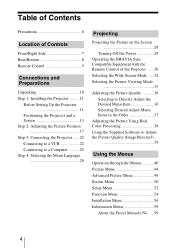
... Before Setting Up the Projector 11 Positioning the Projector and a Screen 13 Step 2: Adjusting the Picture Position 17 Step 3: Connecting the Projector ..... 22 Connecting to a VCR 22 Connecting to a Computer ......... 25 Step 4: Selecting the Menu Language 26 Projecting Projecting the Picture on the Screen 28 Turning Off the Power 29 Operating the BRAVIA Sync Compatible Equipment with...
... Before Setting Up the Projector 11 Positioning the Projector and a Screen 13 Step 2: Adjusting the Picture Position 17 Step 3: Connecting the Projector ..... 22 Connecting to a VCR 22 Connecting to a Computer ......... 25 Step 4: Selecting the Menu Language 26 Projecting Projecting the Picture on the Screen 28 Turning Off the Power 29 Operating the BRAVIA Sync Compatible Equipment with...
Operating Instructions
Page 6
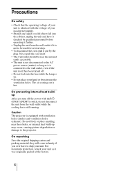
... turned off the power with the ?/1 (ON/STANDBY) switch, do not disconnect the unit from the wall outlet if it is not to the projector. For maximum protection, repack your unit. On repacking Save the original shipping carton and packing material; The air coming out is equipped with ventilation holes.... • The unit is not disconnected to the AC power source (mains) as long as it is connected to ship your unit as it was originally packed at the factory. 6 Caution The projector is hot. Do not block or place anything near these holes, or internal heat build-up may occur...
... turned off the power with the ?/1 (ON/STANDBY) switch, do not disconnect the unit from the wall outlet if it is not to the projector. For maximum protection, repack your unit. On repacking Save the original shipping carton and packing material; The air coming out is equipped with ventilation holes.... • The unit is not disconnected to the AC power source (mains) as long as it is connected to ship your unit as it was originally packed at the factory. 6 Caution The projector is hot. Do not block or place anything near these holes, or internal heat build-up may occur...

Operating Instructions
Page 7
Location of Controls Location of Controls Front/Right Side You can use the buttons on the control panel with the same names as those on the remote control to operate the projector. Press the button and open the cover. Control panel LENS button M/m/
Location of Controls Location of Controls Front/Right Side You can use the buttons on the control panel with the same names as those on the remote control to operate the projector. Press the button and open the cover. Control panel LENS button M/m/
Operating Instructions
Page 10
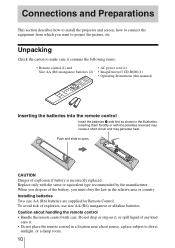
... step on it, or spill liquid of the battery, you want to direct sunlight, or a damp room. 10 Connections and Preparations This section describes how to install the projector and screen, how to connect the equipment from which you must obey the law in the illustration. Push and slide to make sure it...
... step on it, or spill liquid of the battery, you want to direct sunlight, or a damp room. 10 Connections and Preparations This section describes how to install the projector and screen, how to connect the equipment from which you must obey the law in the illustration. Push and slide to make sure it...
Operating Instructions
Page 11
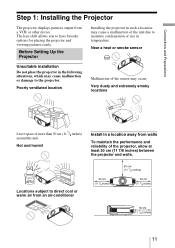
... Near a heat or smoke sensor Unsuitable installation Do not place the projector in the following situations, which may cause a malfunction of the projector, allow at least 30 cm (11 7/8 inches) between the projector and walls. Connections and Preparations Step 1: Installing the Projector The projector displays pictures output from walls To maintain the performance and reliability of...
... Near a heat or smoke sensor Unsuitable installation Do not place the projector in the following situations, which may cause a malfunction of the projector, allow at least 30 cm (11 7/8 inches) between the projector and walls. Connections and Preparations Step 1: Installing the Projector The projector displays pictures output from walls To maintain the performance and reliability of...
Operating Instructions
Page 12
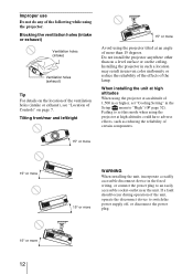
... such a location may result in uneven color uniformity or reduce the reliability of the effects of the following while using the projector at high altitudes could have adverse effects, such as reducing the reliability of Controls" on the ceiling. If a fault should occur during operation of 1,...500 m or higher, set "Cooling Setting" in the fixed wiring, or connect the power plug to switch the power supply off, or disconnect the power plug. 15° or more than on a level surface or on page...
... such a location may result in uneven color uniformity or reduce the reliability of the effects of the following while using the projector at high altitudes could have adverse effects, such as reducing the reliability of Controls" on the ceiling. If a fault should occur during operation of 1,...500 m or higher, set "Cooling Setting" in the fixed wiring, or connect the power plug to switch the power supply off, or disconnect the power plug. 15° or more than on a level surface or on page...
Operating Instructions
Page 13
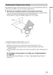
... use the lens shift features. 1 Determine the installation position of the projector and screen. y: Vertical distance between the center of the screen and the center of the projector's lens. Connections and Preparations Positioning the Projector and a Screen The installation distance between the projector and a screen varies depending on the size of the screen or whether...
... use the lens shift features. 1 Determine the installation position of the projector and screen. y: Vertical distance between the center of the screen and the center of the projector's lens. Connections and Preparations Positioning the Projector and a Screen The installation distance between the projector and a screen varies depending on the size of the screen or whether...
Operating Instructions
Page 15
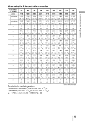
Connections and Preparations When using the 4:3 aspect ratio screen size Screen Size SS (inches) 40 60 80 100 120 150 200 250 300 (mm) 1016 1524 ...
Connections and Preparations When using the 4:3 aspect ratio screen size Screen Size SS (inches) 40 60 80 100 120 150 200 250 300 (mm) 1016 1524 ...

Operating Instructions
Page 17
Step 2: Adjusting the Picture Position Project an image on the screen and then adjust the picture position. 1 ON/STANDBY indicator Connections and Preparations Remote control detector 2 ?/1 (On/ standby) switch 3, 4, 5 Lens button Tip The ?/1 (ON/STANDBY), INPUT, LENS, MENU, and M/m/
Step 2: Adjusting the Picture Position Project an image on the screen and then adjust the picture position. 1 ON/STANDBY indicator Connections and Preparations Remote control detector 2 ?/1 (On/ standby) switch 3, 4, 5 Lens button Tip The ?/1 (ON/STANDBY), INPUT, LENS, MENU, and M/m/
Operating Instructions
Page 19
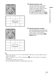
Connections and Preparations 4 Adjust the picture size. Then adjust the size of the picture by pressing the M/m/ Press the LENS button repeatedly until the Lens Zoom adjustment window (test pattern) appears.
Connections and Preparations 4 Adjust the picture size. Then adjust the size of the picture by pressing the M/m/ Press the LENS button repeatedly until the Lens Zoom adjustment window (test pattern) appears.
Operating Instructions
Page 20
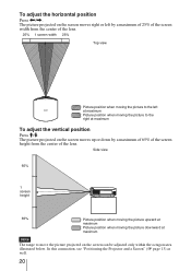
To adjust the horizontal position Press
To adjust the horizontal position Press
Operating Instructions
Page 21
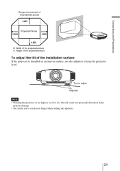
Connections and Preparations Range of movement of the projected picture Projected Picture H: Width of the projected picture V: Height of the projected picture To adjust the tilt of a tilt will result in trapezoidal distortion in the projected image. • Be careful not to catch your finger when turning the adjusters. 21 Turn to keep the projector level. Adjusters Note • Pointing the projector at too high or too low of the installation surface If the projector is installed on an uneven surface, use the adjusters to adjust.
Connections and Preparations Range of movement of the projected picture Projected Picture H: Width of the projected picture V: Height of the projected picture To adjust the tilt of a tilt will result in trapezoidal distortion in the projected image. • Be careful not to catch your finger when turning the adjusters. 21 Turn to keep the projector level. Adjusters Note • Pointing the projector at too high or too low of the installation surface If the projector is installed on an uneven surface, use the adjusters to adjust.
Operating Instructions
Page 22
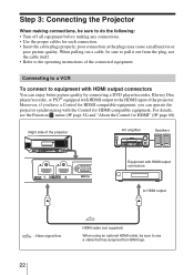
... following: • Turn off all equipment before making connections, be sure to use a cable that has acquired the HDMI logo. 22 Step 3: Connecting the Projector When making any connections. • Use the proper cables for each connection. • Insert the cable plugs properly; Moreover, ... Refer to the HDMI input of the connected equipment. poor connection at the plugs may cause a malfunction or poor picture quality. Connecting to a VCR To connect to equipment with HDMI output connectors You can operate the projector synchronizing with HDMI output to the operating ...
... following: • Turn off all equipment before making connections, be sure to use a cable that has acquired the HDMI logo. 22 Step 3: Connecting the Projector When making any connections. • Use the proper cables for each connection. • Insert the cable plugs properly; Moreover, ... Refer to the HDMI input of the connected equipment. poor connection at the plugs may cause a malfunction or poor picture quality. Connecting to a VCR To connect to equipment with HDMI output connectors You can operate the projector synchronizing with HDMI output to the operating ...
Operating Instructions
Page 23
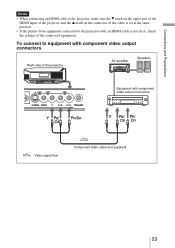
...the same position. • If the picture from equipment connected to equipment with component video output connectors : Video signal flow Component video cable (not supplied) 23 Connections and Preparations Notes • When connecting an HDMI cable to the projector, make sure the V mark on the upper part of... the HDMI input of the projector and the v mark on the connector of the cable is not...
...the same position. • If the picture from equipment connected to equipment with component video output connectors : Video signal flow Component video cable (not supplied) 23 Connections and Preparations Notes • When connecting an HDMI cable to the projector, make sure the V mark on the upper part of... the HDMI input of the projector and the v mark on the connector of the cable is not...
Operating Instructions
Page 24
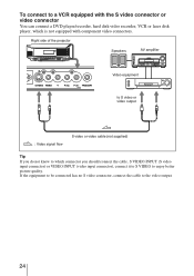
If the equipment to be connected has no S video connector, connect the cable to enjoy better picture quality. Right side of the projector Speakers AV amplifier Video equipment to S video or video output : Video signal flow S video or video cable (not supplied) Tip If you do not ...know to which is not equipped with the S video connector or video connector You can connect a DVD player/recorder, hard ...
If the equipment to be connected has no S video connector, connect the cable to enjoy better picture quality. Right side of the projector Speakers AV amplifier Video equipment to S video or video output : Video signal flow S video or video cable (not supplied) Tip If you do not ...know to which is not equipped with the S video connector or video connector You can connect a DVD player/recorder, hard ...
Operating Instructions
Page 25
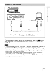
...such as a notebook type, to output the signal to the projector with your computer to output the signal to "Auto" or "Computer." For settings of the computer, consult with the manufacturer of the computer. • If the picture from equipment connected to both computer's display and this equipment, the picture of the... using an optional HDMI cable, be sure to "Computer." (1 pages 53, 66) Notes • When connecting an HDMI cable, make sure the V mark on the upper part of the HDMI input of the projector and the v mark on the connector of the cable is set at the same position. • If...
...such as a notebook type, to output the signal to the projector with your computer to output the signal to "Auto" or "Computer." For settings of the computer, consult with the manufacturer of the computer. • If the picture from equipment connected to both computer's display and this equipment, the picture of the... using an optional HDMI cable, be sure to "Computer." (1 pages 53, 66) Notes • When connecting an HDMI cable, make sure the V mark on the upper part of the HDMI input of the projector and the v mark on the connector of the cable is set at the same position. • If...
Operating Instructions
Page 27
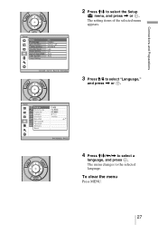
The setting items of the selected menu appears. 3 Press M/m to select the Setup menu, and press , or . Connections and Preparations 2 Press M/m to select "Language," and press , or . 4 Press M/m/
The setting items of the selected menu appears. 3 Press M/m to select the Setup menu, and press , or . Connections and Preparations 2 Press M/m to select "Language," and press , or . 4 Press M/m/
Operating Instructions
Page 28
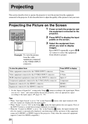
...Input-A* Component HDMI 1 HDMI 2 * Set the "Input-A Signal Sel." It also describes how to adjust the quality of the projector. (Only when the connected equipment supports Control for HDMI compatible.) 28 When you want to display images. Projecting the Picture on the Screen 1 Power on both ...the projector and the equipment connected to the projector. 2 Press INPUT to "Off" in the Function menu, the input terminal with the operation of the equipment connected to HDMI 1 or HDMI 2 input of the picture to the signal...
...Input-A* Component HDMI 1 HDMI 2 * Set the "Input-A Signal Sel." It also describes how to adjust the quality of the projector. (Only when the connected equipment supports Control for HDMI compatible.) 28 When you want to display images. Projecting the Picture on the Screen 1 Power on both ...the projector and the equipment connected to the projector. 2 Press INPUT to "Off" in the Function menu, the input terminal with the operation of the equipment connected to HDMI 1 or HDMI 2 input of the picture to the signal...


