Operating Instructions
Page 3
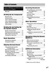
...cords 6 Antenna hookups 7 Audio component hookups 8 Video component hookups 9 Digital component hookups 10 Other hookups 11 Hooking Up and Setting Up the Speaker System Speaker system hookups 12 Performing initial setup operations ..... 14 Multi channel surround...Enjoying Surround Sound Using only the front speakers (2 Channel Stereo 22 Enjoying higher fidelity sound 22 Selecting a sound field 23 Understanding the multi channel surround displays 25 Customizing sound fields 26 Receiving Broadcasts Storing FM stations automatically (AUTOBETICAL)1 28 Direct tuning 28 Automatic tuning...
...cords 6 Antenna hookups 7 Audio component hookups 8 Video component hookups 9 Digital component hookups 10 Other hookups 11 Hooking Up and Setting Up the Speaker System Speaker system hookups 12 Performing initial setup operations ..... 14 Multi channel surround...Enjoying Surround Sound Using only the front speakers (2 Channel Stereo 22 Enjoying higher fidelity sound 22 Selecting a sound field 23 Understanding the multi channel surround displays 25 Customizing sound fields 26 Receiving Broadcasts Storing FM stations automatically (AUTOBETICAL)1 28 Direct tuning 28 Automatic tuning...
Operating Instructions
Page 6
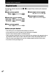
white (left, audio) to red. • When you hook up the components (pages 8 - 10). E are completed. • Be sure to make connections firmly to avoid hum and noise. • When connecting an audio/video ..., be sure to match the color-coded pins to the appropriate jacks on the components: yellow (video) to yellow; and red (right, audio) to white; Hooking Up the Components Required cords The following optional connection cords A - A Audio cord (not supplied) White (L) Red (R) B Audio/video cord (not supplied) Yellow (video) White (L/audio...
white (left, audio) to red. • When you hook up the components (pages 8 - 10). E are completed. • Be sure to make connections firmly to avoid hum and noise. • When connecting an audio/video ..., be sure to match the color-coded pins to the appropriate jacks on the components: yellow (video) to yellow; and red (right, audio) to white; Hooking Up the Components Required cords The following optional connection cords A - A Audio cord (not supplied) White (L) Red (R) B Audio/video cord (not supplied) Yellow (video) White (L/audio...
Operating Instructions
Page 7
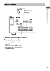
Notes on the area code. Hooking Up the Components Antenna hookups AM loop antenna (supplied) FM wire antenna (supplied) DIGITAL OPTICAL VIDEO 2 IN DVD IN COAXIAL ANTENNA AM y FM 75Ω COAXIAL MONITOR VIDEO IN VIDEO IN VIDEO OUT VIDEO IN VIDEO OUT L AUDIO OUT R IN CD OUT IN ...* * The shape of the connector varies depending on antenna hookups • To prevent noise pickup, keep the AM loop antenna away from the receiver and other components. • Be sure to fully extend the FM wire antenna. • After connecting the FM wire antenna, keep it as horizontal as possible. 7GB
Notes on the area code. Hooking Up the Components Antenna hookups AM loop antenna (supplied) FM wire antenna (supplied) DIGITAL OPTICAL VIDEO 2 IN DVD IN COAXIAL ANTENNA AM y FM 75Ω COAXIAL MONITOR VIDEO IN VIDEO IN VIDEO OUT VIDEO IN VIDEO OUT L AUDIO OUT R IN CD OUT IN ...* * The shape of the connector varies depending on antenna hookups • To prevent noise pickup, keep the AM loop antenna away from the receiver and other components. • Be sure to fully extend the FM wire antenna. • After connecting the FM wire antenna, keep it as horizontal as possible. 7GB
Operating Instructions
Page 9
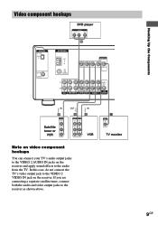
Hooking Up the Components Ç Ç Video component hookups DVD player OUTPUT AUDIO OUT R L VIDEO OUT B DIGITAL OPTICAL VIDEO 2 IN DVD IN COAXIAL ANTENNA AM y FM 75Ω COAXIAL MONITOR VIDEO IN VIDEO IN VIDEO OUT VIDEO IN VIDEO OUT L AUDIO OUT R IN CD OUT IN AUDIO IN AUDIO IN AUDIO ... VIDEO IN TV monitor Note on video component hookups You can connect your TV's audio output jacks to the VIDEO 2 AUDIO IN jacks on the receiver. If you are connecting a separate satellite tuner, connect both the audio and video output jacks to the audio from the TV. In this case, do...
Hooking Up the Components Ç Ç Video component hookups DVD player OUTPUT AUDIO OUT R L VIDEO OUT B DIGITAL OPTICAL VIDEO 2 IN DVD IN COAXIAL ANTENNA AM y FM 75Ω COAXIAL MONITOR VIDEO IN VIDEO IN VIDEO OUT VIDEO IN VIDEO OUT L AUDIO OUT R IN CD OUT IN AUDIO IN AUDIO IN AUDIO ... VIDEO IN TV monitor Note on video component hookups You can connect your TV's audio output jacks to the VIDEO 2 AUDIO IN jacks on the receiver. If you are connecting a separate satellite tuner, connect both the audio and video output jacks to the audio from the TV. In this case, do...

Operating Instructions
Page 11
... a wall outlet, connect the speaker system to the local power supply voltage. If not, use a screwdriver to set to the receiver (page 12). Hooking Up the Components Other hookups AC power cord RL RL RL RL FRONT CENTER SURROUND SPEAKERS IMPEDANCE USE 8 - 16Ω b To a wall .../ video components to a wall outlet. VOLTAGE SELECTOR 120V 220V 240V Connecting the AC power cord Before connecting the AC power cord of your receiver has a voltage selector on the rear panel, check that the voltage selector is set the selector to the correct position before connecting the AC...
... a wall outlet, connect the speaker system to the local power supply voltage. If not, use a screwdriver to set to the receiver (page 12). Hooking Up the Components Other hookups AC power cord RL RL RL RL FRONT CENTER SURROUND SPEAKERS IMPEDANCE USE 8 - 16Ω b To a wall .../ video components to a wall outlet. VOLTAGE SELECTOR 120V 220V 240V Connecting the AC power cord Before connecting the AC power cord of your receiver has a voltage selector on the rear panel, check that the voltage selector is set the selector to the correct position before connecting the AC...

Operating Instructions
Page 12
Hooking Up and Setting Up the Speaker System Speaker system hookups Required cords A Speaker cords (supplied) (+) (-) B Monaural audio cord (supplied) Black Active sub woofer INPUT Front speaker (R) Front speaker (L) e Ee E b B To a wall outlet (Switch the power (POWER) to off before connecting the power cord.) A A MONITOR VIDEO OUT AUDIO OUT SUB WOOFER RL RL RL RL FRONT CENTER SURROUND SPEAKERS IMPEDANCE USE 8 - 16Ω 12GB E A A A e Ee Ee Center speaker Surround speaker Surround speaker (R) (L)
Hooking Up and Setting Up the Speaker System Speaker system hookups Required cords A Speaker cords (supplied) (+) (-) B Monaural audio cord (supplied) Black Active sub woofer INPUT Front speaker (R) Front speaker (L) e Ee E b B To a wall outlet (Switch the power (POWER) to off before connecting the power cord.) A A MONITOR VIDEO OUT AUDIO OUT SUB WOOFER RL RL RL RL FRONT CENTER SURROUND SPEAKERS IMPEDANCE USE 8 - 16Ω 12GB E A A A e Ee Ee Center speaker Surround speaker Surround speaker (R) (L)

Operating Instructions
Page 13
... Twist the stripped ends of the receiver. After connecting all the speakers are touching the rear panel of the speaker cords about 10 mm (2/3 inch). Be sure to match the speaker cord to the appropriate terminal on outputting a test tone, see page 18. Hooking Up and Setting Up the Speaker System... volume remains at the bottom of the speaker cord Stripped cords are not fully attached and are connected correctly. When you turn off the receiver. To avoid damaging your speakers Make sure that all the components, speakers, and AC power cord, output a test tone to check that you...
... Twist the stripped ends of the receiver. After connecting all the speakers are touching the rear panel of the speaker cords about 10 mm (2/3 inch). Be sure to match the speaker cord to the appropriate terminal on outputting a test tone, see page 18. Hooking Up and Setting Up the Speaker System... volume remains at the bottom of the speaker cord Stripped cords are not fully attached and are connected correctly. When you turn off the receiver. To avoid damaging your speakers Make sure that all the components, speakers, and AC power cord, output a test tone to check that you...
Operating Instructions
Page 14
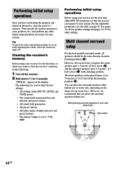
...(to set to the side, depending on page 51. Performing initial setup operations Before using your receiver for the first time, or when you have hooked up the speakers and turned on the power, clear the receiver's memory. "INITIAL" appears in the SET UP, LEVEL and TONE menus. • The ... parameters so that you place the surround speakers behind you place the center speaker up to 23 feet) from the listening position (A). However, the receiver lets you or to "VOL MIN". For the adjustable parameters, see the table on the shape of input selectors and preset stations. •...
...(to set to the side, depending on page 51. Performing initial setup operations Before using your receiver for the first time, or when you have hooked up the speakers and turned on the power, clear the receiver's memory. "INITIAL" appears in the SET UP, LEVEL and TONE menus. • The ... parameters so that you place the surround speakers behind you place the center speaker up to 23 feet) from the listening position (A). However, the receiver lets you or to "VOL MIN". For the adjustable parameters, see the table on the shape of input selectors and preset stations. •...
Operating Instructions
Page 15
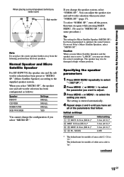
... FRONT CENTER SURROUND SUB WOOFER Settings SMALL SMALL SMALL YES You cannot change the speaker system, select "NORM. SP." (page 17). Caution When you use Sony's Micro Satellite Speakers, select "MICRO SP.". XXXX Initial setting 3.0 m (10 ft.)* 3.0 m (10 ft.)* 3.0 m (10 ft.)* LOW * The... you select "MICRO SP.". The speaker may not obtain the correct soundstage. Initial settings Parameter L R DIST. X.X m (XX ft.)* SL SR DIST. Hooking Up and Setting Up the Speaker System When placing surround speakers behind you want . The setting is "m". X.X m (XX ft.)* SL SR PL. Normal ...
... FRONT CENTER SURROUND SUB WOOFER Settings SMALL SMALL SMALL YES You cannot change the speaker system, select "NORM. SP." (page 17). Caution When you use Sony's Micro Satellite Speakers, select "MICRO SP.". XXXX Initial setting 3.0 m (10 ft.)* 3.0 m (10 ft.)* 3.0 m (10 ft.)* LOW * The... you select "MICRO SP.". The speaker may not obtain the correct soundstage. Initial settings Parameter L R DIST. X.X m (XX ft.)* SL SR DIST. Hooking Up and Setting Up the Speaker System When placing surround speakers behind you want . The setting is "m". X.X m (XX ft.)* SL SR PL. Normal ...

Operating Instructions
Page 17
... redirection circuitry and output the center channel bass frequencies from the surround speakers and the sound of the Digital Cinema Sound modes with virtual elements. Hooking Up and Setting Up the Speaker System Tip The surround speaker placement parameter is distorted, or you do not connect a sub woofer, select "NO...
... redirection circuitry and output the center channel bass frequencies from the surround speakers and the sound of the Digital Cinema Sound modes with virtual elements. Hooking Up and Setting Up the Speaker System Tip The surround speaker placement parameter is distorted, or you do not connect a sub woofer, select "NO...
Operating Instructions
Page 19
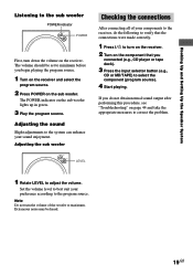
Hooking Up and Setting Up the Speaker System Listening to the sub woofer POWER indicator POWER First, turn the volume of your components to the receiver, do not obtain normal sound output after performing this procedure, see "Troubleshooting" on page 44 and take the appropriate measures ...tape deck). 3 Press the input selector button (e.g., CD or MD/TAPE) to maximum. LEVEL 1 Rotate LEVEL to turn on the receiver. 2 Turn on the receiver. The POWER indicator on the sub woofer. Set the volume level to the program source. Adjusting the sound Slight adjustments to the system...
Hooking Up and Setting Up the Speaker System Listening to the sub woofer POWER indicator POWER First, turn the volume of your components to the receiver, do not obtain normal sound output after performing this procedure, see "Troubleshooting" on page 44 and take the appropriate measures ...tape deck). 3 Press the input selector button (e.g., CD or MD/TAPE) to maximum. LEVEL 1 Rotate LEVEL to turn on the receiver. 2 Turn on the receiver. The POWER indicator on the sub woofer. Set the volume level to the program source. Adjusting the sound Slight adjustments to the system...


