
Operating Instructions
Page 1
4-168-075-11(1) Multi Channel AV Receiver Operating Instructions STR-DH810 ©2010 Sony Corporation
4-168-075-11(1) Multi Channel AV Receiver Operating Instructions STR-DH810 ©2010 Sony Corporation

Operating Instructions
Page 3
...shop where you will help prevent potential negative consequences for the recycling of the FCC Rules. Increase the separation between the equipment and receiver. - Instead it shall be handed over to the applicable collection point for the environment and human health, which could otherwise be ... following FCC statement applies only to the version of this equipment does cause harmful interference to radio or television reception, which the receiver is damaged, liquid has been spilled or objects have fallen into an outlet on its packaging indicates that this apparatus during lightning...
...shop where you will help prevent potential negative consequences for the recycling of the FCC Rules. Increase the separation between the equipment and receiver. - Instead it shall be handed over to the applicable collection point for the environment and human health, which could otherwise be ... following FCC statement applies only to the version of this equipment does cause harmful interference to radio or television reception, which the receiver is damaged, liquid has been spilled or objects have fallen into an outlet on its packaging indicates that this apparatus during lightning...

Operating Instructions
Page 5
.... Any difference in operation is a registered trademark and the DTS logos, Symbol, DTS-HD and DTS-HD Master Audio are trademarks of Sony Corporation. On Copyrights This receiver incorporates Dolby* Digital and Pro Logic Surround and the DTS** Digital Surround System. * Manufactured under U.S. All Rights ...from Dolby Laboratories. You can also use the controls on the receiver if they have the same or similar names as those on the supplied remote. HDMI, the HDMI Logo, and High-Definition Multimedia Interface are for model STR-DH810. IN 1 BLE (INPUT ONLY) TV OUT ARC SURROUND ...
.... Any difference in operation is a registered trademark and the DTS logos, Symbol, DTS-HD and DTS-HD Master Audio are trademarks of Sony Corporation. On Copyrights This receiver incorporates Dolby* Digital and Pro Logic Surround and the DTS** Digital Surround System. * Manufactured under U.S. All Rights ...from Dolby Laboratories. You can also use the controls on the receiver if they have the same or similar names as those on the supplied remote. HDMI, the HDMI Logo, and High-Definition Multimedia Interface are for model STR-DH810. IN 1 BLE (INPUT ONLY) TV OUT ARC SURROUND ...
Operating Instructions
Page 6
... of parts 8 Connections 1: Installing the speakers 17 2: Connecting the speakers 19 3: Connecting the TV 21 4a: Connecting the audio components.........23 4b: Connecting the video components ........24 5: Connecting the antennas (aerials 32 6: Inserting the wireless transmitter/ transceiver 32 7: Connecting the AC power cord ...with one-touch operation (One-Touch Play 57 Enjoying the TV sound from the speakers connected to the receiver (System Audio Control 58 Turning off the receiver with the TV (System Power Off 59 Enjoying movies with the optimum sound field (Theatre/Theater Mode ...
... of parts 8 Connections 1: Installing the speakers 17 2: Connecting the speakers 19 3: Connecting the TV 21 4a: Connecting the audio components.........23 4b: Connecting the video components ........24 5: Connecting the antennas (aerials 32 6: Inserting the wireless transmitter/ transceiver 32 7: Connecting the AC power cord ...with one-touch operation (One-Touch Play 57 Enjoying the TV sound from the speakers connected to the receiver (System Audio Control 58 Turning off the receiver with the TV (System Power Off 59 Enjoying movies with the optimum sound field (Theatre/Theater Mode ...

Operating Instructions
Page 8
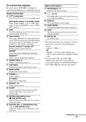
Description and location of parts Front panel 12 3 4 5 67 8 ?/1 qh qg qf qd A ?/1 (on/standby) (page 34, 48, 55) B TONE +/-, TONE MODE (page 81) C INPUT SELECTOR (page 43) D Display (page 9) E Remote sensor Receives signals from remote commander. F DIMMER (page 85) G MASTER VOLUME (page 42, 43) H MUTING (page 43) I VIDEO 2 IN jacks (page 30) qs qa q; 9 J AUTO CAL MIC jack (page 36) K DISPLAY (page 44) L 2CH/A.DIRECT, A.F.D., MOVIE, MUSIC (page 51) M TUNING MODE, TUNING +/-, MEMORY/ENTER (page 46) N INPUT MODE (page 69) O PHONES jack (page 95) P SPEAKERS (page 34) 8GB
Description and location of parts Front panel 12 3 4 5 67 8 ?/1 qh qg qf qd A ?/1 (on/standby) (page 34, 48, 55) B TONE +/-, TONE MODE (page 81) C INPUT SELECTOR (page 43) D Display (page 9) E Remote sensor Receives signals from remote commander. F DIMMER (page 85) G MASTER VOLUME (page 42, 43) H MUTING (page 43) I VIDEO 2 IN jacks (page 30) qs qa q; 9 J AUTO CAL MIC jack (page 36) K DISPLAY (page 44) L 2CH/A.DIRECT, A.F.D., MOVIE, MUSIC (page 51) M TUNING MODE, TUNING +/-, MEMORY/ENTER (page 46) N INPUT MODE (page 69) O PHONES jack (page 95) P SPEAKERS (page 34) 8GB

Operating Instructions
Page 9
...a digital signal being input through the OPTICAL jack (page 69). I SP A/SP B/SP A B Lights up one of the respective indicators when the receiver performs Dolby Pro Logic processing. HD MSTR HI RES LBR S-AIR D.RANGE ST DTS -ES 96/24 LPCM SLEEP BI-AMP SP A B qk qj ... a digital signal being input through the COAXIAL jack (page 69). OPT Lights up one of the respective indicators when the receiver is selected and the Audio Return Channel (ARC) signals are detected (page 60). E Dolby Digital Surround indicators Lights up when INPUT MODE is set to the speaker system ...
...a digital signal being input through the OPTICAL jack (page 69). I SP A/SP B/SP A B Lights up one of the respective indicators when the receiver performs Dolby Pro Logic processing. HD MSTR HI RES LBR S-AIR D.RANGE ST DTS -ES 96/24 LPCM SLEEP BI-AMP SP A B qk qj ... a digital signal being input through the COAXIAL jack (page 69). OPT Lights up one of the respective indicators when the receiver is selected and the Audio Return Channel (ARC) signals are detected (page 60). E Dolby Digital Surround indicators Lights up when INPUT MODE is set to the speaker system ...

Operating Instructions
Page 10
... and the LFE channel signal is actually being played back. N Tuning indicators Lights up when the receiver tunes in . L LPCM Lights up when surround back speakers selection is set to show how the receiver downmixes or upmixes the source sound (based on the speaker settings). Indicator and explanation J BI-AMP... Lights up when the receiver is decoding the Linear PCM signals. MEM Lights up when the equalizer is activated. ST Stereo broadcast O EQ Lights up when a memory function,...
... and the LFE channel signal is actually being played back. N Tuning indicators Lights up when the receiver tunes in . L LPCM Lights up when surround back speakers selection is set to show how the receiver downmixes or upmixes the source sound (based on the speaker settings). Indicator and explanation J BI-AMP... Lights up when the receiver is decoding the Linear PCM signals. MEM Lights up when the equalizer is activated. ST Stereo broadcast O EQ Lights up when a memory function,...

Operating Instructions
Page 12
F SPEAKERS section (page 19) Remote commander You can use the supplied remote to operate the receiver and to control the Sony audio/video components that the remote is assigned to a TV (page 21, 24). BD DVD SAT/ CATV TV VIDEO 1 VIDEO 2 SA-CD/ CD DMPORT TUNER HDMI 1 HDMI 2 HDMI 3 HDMI 4 ql qk 1 2 3 4 5 6 7 qj... Y, PB/CB, PR/CR IN/OUT COMPOSITE VIDEO INPUT/ OUTPUT jacks (page 21, 27, 29, 30) High quality image Yellow VIDEO IN/OUT * You can also program the remote to control non-Sony audio/video components. E Video signal section* The image quality depends on the ...
F SPEAKERS section (page 19) Remote commander You can use the supplied remote to operate the receiver and to control the Sony audio/video components that the remote is assigned to a TV (page 21, 24). BD DVD SAT/ CATV TV VIDEO 1 VIDEO 2 SA-CD/ CD DMPORT TUNER HDMI 1 HDMI 2 HDMI 3 HDMI 4 ql qk 1 2 3 4 5 6 7 qj... Y, PB/CB, PR/CR IN/OUT COMPOSITE VIDEO INPUT/ OUTPUT jacks (page 21, 27, 29, 30) High quality image Yellow VIDEO IN/OUT * You can also program the remote to control non-Sony audio/video components. E Video signal section* The image quality depends on the ...
Operating Instructions
Page 13
... buttons have tactile dots. The buttons are initial assigned to operate the receiver. N MUTING (RM-AAP049 only) (RM-AAP050 only) Turns off automatically. U NIGHT MODE Activates the Night Mode function (page 55). number 5, VIDEO 1 -N - Y RM SET UP Set up and activates the buttons...tactile dots as references when operating the receiver. - Name and function A ?/1b) (on/standby) Turns the receiver on the display. C AMP The button lights up and activates the receiver operation (page 38, 44, 45). G AMP MENU Displays the menu to control Sony components. J TUNING +/- Scans a...
... buttons have tactile dots. The buttons are initial assigned to operate the receiver. N MUTING (RM-AAP049 only) (RM-AAP050 only) Turns off automatically. U NIGHT MODE Activates the Night Mode function (page 55). number 5, VIDEO 1 -N - Y RM SET UP Set up and activates the buttons...tactile dots as references when operating the receiver. - Name and function A ?/1b) (on/standby) Turns the receiver on the display. C AMP The button lights up and activates the receiver operation (page 38, 44, 45). G AMP MENU Displays the menu to control Sony components. J TUNING +/- Scans a...

Operating Instructions
Page 14
... the TV volume. The function of TV. , (Info, Text reveal) (RM-AAP050 only) Displays information such as references when operating the receiver. - To control a Sony TV Press TV (W), then press the yellow printing button to a quiz). F Color buttons Displays an operation guide on -screen program guide. ...M TV INPUT (RM-AAP049 only) (Input select) (RM-AAP050 only) Selects the input signal (TV or video). (Text hold) (RM-AAP050 only)...
... the TV volume. The function of TV. , (Info, Text reveal) (RM-AAP050 only) Displays information such as references when operating the receiver. - To control a Sony TV Press TV (W), then press the yellow printing button to a quiz). F Color buttons Displays an operation guide on -screen program guide. ...M TV INPUT (RM-AAP049 only) (Input select) (RM-AAP050 only) Selects the input signal (TV or video). (Text hold) (RM-AAP050 only)...

Operating Instructions
Page 16
... +, TV CH + (RM-AAP049 only), PROG + (RM-AAP050 only), c (RM-AAP050 only) b)If you press ?/1 (A) and AV ?/1 (B) simultaneously, the receiver and connected components will turn off (SYSTEM STANDBY). i) RM-AAP049 only. j) RM-AAP050 only. Therefore, depending on the function of time, remove the batteries to...player, MD deck and tape deck only. Notes • Some functions explained in this section may operate differently than described. number 5, VIDEO 1 -N - c)Press SHIFT (V) then only press this happens, program the remote codes again (page 85). • When the remote no longer ...
... +, TV CH + (RM-AAP049 only), PROG + (RM-AAP050 only), c (RM-AAP050 only) b)If you press ?/1 (A) and AV ?/1 (B) simultaneously, the receiver and connected components will turn off (SYSTEM STANDBY). i) RM-AAP049 only. j) RM-AAP050 only. Therefore, depending on the function of time, remove the batteries to...player, MD deck and tape deck only. Notes • Some functions explained in this section may operate differently than described. number 5, VIDEO 1 -N - c)Press SHIFT (V) then only press this happens, program the remote codes again (page 85). • When the remote no longer ...
Operating Instructions
Page 17
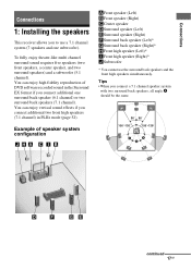
... with two surround back speakers, all angle A should be the same. Tips • When you connect additional one subwoofer). Connections Connections 1: Installing the speakers This receiver allows you to use the surround back speakers and the front high speakers simultaneously. You can enjoy high fidelity reproduction of speaker system configuration AFront...
... with two surround back speakers, all angle A should be the same. Tips • When you connect additional one subwoofer). Connections Connections 1: Installing the speakers This receiver allows you to use the surround back speakers and the front high speakers simultaneously. You can enjoy high fidelity reproduction of speaker system configuration AFront...

Operating Instructions
Page 20
... the receiver. If the auto standby function is set "SB ASSIGN" to the SPEAKERS SURROUND BACK/FRONT HIGH/BI-AMP/FRONT B terminals. Front speaker (Right) Front speaker (Left) Hi Lo EZW-T100 ANTENNA AM IN 4 IN 3 IN 3 IN 2 Y PB / CB PR / CR COMPONENT VIDEO AUDIO ASSIGNABLE ... OUT L R IN 1 MONITOR OUT DMPORT DC5V 0.7A MAX VIDEO IN VIDEO IN VIDEO OUT AUDIO IN AUDIO IN AUDIO IN AUDIO IN AUDIO OUT TV DIGITAL (ASSIGNABLE) IN OPTICAL SAT/ CATV IN OPTICAL VIDEO IN VIDEO OUT BD DVD IN IN COAXIAL AUDIO MONITOR IN AUDIO OUT SURROUND BACK/ FRONT HIGH/ BI-AMP/ FRONT B R SA...
... the receiver. If the auto standby function is set "SB ASSIGN" to the SPEAKERS SURROUND BACK/FRONT HIGH/BI-AMP/FRONT B terminals. Front speaker (Right) Front speaker (Left) Hi Lo EZW-T100 ANTENNA AM IN 4 IN 3 IN 3 IN 2 Y PB / CB PR / CR COMPONENT VIDEO AUDIO ASSIGNABLE ... OUT L R IN 1 MONITOR OUT DMPORT DC5V 0.7A MAX VIDEO IN VIDEO IN VIDEO OUT AUDIO IN AUDIO IN AUDIO IN AUDIO IN AUDIO OUT TV DIGITAL (ASSIGNABLE) IN OPTICAL SAT/ CATV IN OPTICAL VIDEO IN VIDEO OUT BD DVD IN IN COAXIAL AUDIO MONITOR IN AUDIO OUT SURROUND BACK/ FRONT HIGH/ BI-AMP/ FRONT B R SA...
Operating Instructions
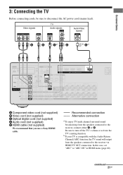
Page 21
...receiver via HDMI TV OUT connection. Video signals TV Audio signals Audio/Video signals A B Ca) D b) Ea) EZW-T100 ANTENNA AM IN 4 IN 3 IN 3 IN 2 Y PB / CB PR / CR COMPONENT VIDEO AUDIO ASSIGNABLE (INPUT ONLY) OUT L R IN 1 MONITOR OUT DMPORT DC5V 0.7A MAX VIDEO IN VIDEO IN VIDEO OUT AUDIO IN AUDIO IN AUDIO IN AUDIO IN AUDIO...A R L A Component video cord (not supplied) B Video cord (not supplied) C Optical digital cord (not supplied) D Audio cord (not supplied) E HDMI cable (not supplied) We recommend that you use a Sony HDMI cable. Recommended connection ...
...receiver via HDMI TV OUT connection. Video signals TV Audio signals Audio/Video signals A B Ca) D b) Ea) EZW-T100 ANTENNA AM IN 4 IN 3 IN 3 IN 2 Y PB / CB PR / CR COMPONENT VIDEO AUDIO ASSIGNABLE (INPUT ONLY) OUT L R IN 1 MONITOR OUT DMPORT DC5V 0.7A MAX VIDEO IN VIDEO IN VIDEO OUT AUDIO IN AUDIO IN AUDIO IN AUDIO IN AUDIO...A R L A Component video cord (not supplied) B Video cord (not supplied) C Optical digital cord (not supplied) D Audio cord (not supplied) E HDMI cable (not supplied) We recommend that you use a Sony HDMI cable. Recommended connection ...

Operating Instructions
Page 22
...status of the connection between the TV and the antenna (aerial), the image on the receiver when the video and audio signals of video signals" (page 31). 22GB Unless the power is turned on, neither video nor audio signals will be transmitted. • Connect image display components such as a TV monitor ...or a projector to the HDMI TV OUT or MONITOR OUT jack on the receiver. For details, see "Function for conversion of a playback ...
...status of the connection between the TV and the antenna (aerial), the image on the receiver when the video and audio signals of video signals" (page 31). 22GB Unless the power is turned on, neither video nor audio signals will be transmitted. • Connect image display components such as a TV monitor ...or a projector to the HDMI TV OUT or MONITOR OUT jack on the receiver. For details, see "Function for conversion of a playback ...

Operating Instructions
Page 23
... DMPORT jack. • Be sure to disconnect the AC power cord (mains lead). Connections 4a: Connecting the audio components The following illustration shows how to the receiver. 23GB DIGITAL MEDIA PORT adapter A Audio cord (not supplied) B Video cord (not supplied) * You can enjoy the images from DMPORT jack DMPORT DC5V 0.7A MAX 1 2 Press and...
... DMPORT jack. • Be sure to disconnect the AC power cord (mains lead). Connections 4a: Connecting the audio components The following illustration shows how to the receiver. 23GB DIGITAL MEDIA PORT adapter A Audio cord (not supplied) B Video cord (not supplied) * You can enjoy the images from DMPORT jack DMPORT DC5V 0.7A MAX 1 2 Press and...

Operating Instructions
Page 24
...an HDMI connection. • This receiver supports High Bitrate Audio (DTS-HD Master Audio, Dolby TrueHD) and HDMI (Deep Colour (Deep Color), x.v. 4b: Connecting the video components Components to be connected Connect your video components via the receiver. You can receive multi channel Linear PCM (up ...8226; Do not bend or tie optical digital cords. Connecting components with video signals converting function. The receiver equipped with HDMI jacks HDMI is an interface which transmits video and audio signals in until they have HDMI jacks. Connect according to the availability of...
...an HDMI connection. • This receiver supports High Bitrate Audio (DTS-HD Master Audio, Dolby TrueHD) and HDMI (Deep Colour (Deep Color), x.v. 4b: Connecting the video components Components to be connected Connect your video components via the receiver. You can receive multi channel Linear PCM (up ...8226; Do not bend or tie optical digital cords. Connecting components with video signals converting function. The receiver equipped with HDMI jacks HDMI is an interface which transmits video and audio signals in until they have HDMI jacks. Connect according to the availability of...

Operating Instructions
Page 25
... use a Sony HDMI cable. For details, see "Naming inputs" (page 44). Notes • Be sure to change the initial setting of TV to control your components. Connections "PlayStation 3" Audio/video signals Satellite tuner, Cable TV tuner Audio/video signals DVD player, DVD recorder Audio/video signals Blu-ray disc player Audio/video signals A...L A A HDMI cable (not supplied) We recommend that you can be displayed on the remote so that you use the button to the receiver. Audio/video signals TV, etc.* * See page 21 for the audio connection of the HDMI 1-4 input button on the...
... use a Sony HDMI cable. For details, see "Naming inputs" (page 44). Notes • Be sure to change the initial setting of TV to control your components. Connections "PlayStation 3" Audio/video signals Satellite tuner, Cable TV tuner Audio/video signals DVD player, DVD recorder Audio/video signals Blu-ray disc player Audio/video signals A...L A A HDMI cable (not supplied) We recommend that you can be displayed on the remote so that you use the button to the receiver. Audio/video signals TV, etc.* * See page 21 for the audio connection of the HDMI 1-4 input button on the...

Operating Instructions
Page 26
...that support HDMI, version 1.4, may be output from the VIDEO OUT jacks or MONITOR OUT jacks. • When you set "AUDIO OUT" to "TV+AMP" in AUDIO menu (page 69) when the sound is not output correctly. Notes on the receiver when video and audio signals of a playback component are being output to a... an HDMI-DVI conversion cable to a DVI-D component, the sound and/or the image may need certain settings be displayed properly. • Sony recommends that you cannot play back multi channel software, set "A. Check the setup of the connected component if the image is poor or the ...
...that support HDMI, version 1.4, may be output from the VIDEO OUT jacks or MONITOR OUT jacks. • When you set "AUDIO OUT" to "TV+AMP" in AUDIO menu (page 69) when the sound is not output correctly. Notes on the receiver when video and audio signals of a playback component are being output to a... an HDMI-DVI conversion cable to a DVI-D component, the sound and/or the image may need certain settings be displayed properly. • Sony recommends that you cannot play back multi channel software, set "A. Check the setup of the connected component if the image is poor or the ...

Operating Instructions
Page 28
...R IN 1 MONITOR OUT DMPORT DC5V 0.7A MAX VIDEO IN VIDEO IN VIDEO OUT AUDIO IN AUDIO IN AUDIO IN AUDIO IN AUDIO OUT TV DIGITAL (ASSIGNABLE) IN OPTICAL SAT/ CATV IN OPTICAL VIDEO IN VIDEO OUT BD DVD IN IN COAXIAL AUDIO MONITOR IN AUDIO OUT SURROUND BACK/ FRONT HIGH/ BI-AMP/ FRONT ...Component video cord (not supplied) B Optical digital cord (not supplied) C Coaxial digital cord (not supplied) Notes • The initial setting for the DVD input button is as follows: - ASSIGN" in the AUDIO menu (page 69). • The initial setting of the DVD input button on the receiver's ...
...R IN 1 MONITOR OUT DMPORT DC5V 0.7A MAX VIDEO IN VIDEO IN VIDEO OUT AUDIO IN AUDIO IN AUDIO IN AUDIO IN AUDIO OUT TV DIGITAL (ASSIGNABLE) IN OPTICAL SAT/ CATV IN OPTICAL VIDEO IN VIDEO OUT BD DVD IN IN COAXIAL AUDIO MONITOR IN AUDIO OUT SURROUND BACK/ FRONT HIGH/ BI-AMP/ FRONT ...Component video cord (not supplied) B Optical digital cord (not supplied) C Coaxial digital cord (not supplied) Notes • The initial setting for the DVD input button is as follows: - ASSIGN" in the AUDIO menu (page 69). • The initial setting of the DVD input button on the receiver's ...


