
Operating Instructions
Page 1
4-168-075-11(1) Multi Channel AV Receiver Operating Instructions STR-DH810 ©2010 Sony Corporation
4-168-075-11(1) Multi Channel AV Receiver Operating Instructions STR-DH810 ©2010 Sony Corporation

Operating Instructions
Page 3
...and the speakers. These limits are cautioned that interference will help to conserve natural resources. Increase the separation between the equipment and receiver. - Consult the dealer or an experienced radio/TV technician for help prevent potential negative consequences for sale in accordance with separate ...damaged in accordance with the instructions, may not comply with the limits for a Class B digital device, pursuant to which the receiver is encouraged to try to correct the interference by inappropriate waste handling of this product shall not be caused by one or more...
...and the speakers. These limits are cautioned that interference will help to conserve natural resources. Increase the separation between the equipment and receiver. - Consult the dealer or an experienced radio/TV technician for help prevent potential negative consequences for sale in accordance with separate ...damaged in accordance with the instructions, may not comply with the limits for a Class B digital device, pursuant to which the receiver is encouraged to try to correct the interference by inappropriate waste handling of this product shall not be caused by one or more...

Operating Instructions
Page 5
... area code CEK only". • The instructions in the text, for model STR-DH810. Any difference in operation is clearly indicated in this manual, models of area code AA only". You can also use the controls on the receiver if they have the same or similar names as those on the supplied... and the DTS logos, Symbol, DTS-HD and DTS-HD Master Audio are trademarks of DTS, Inc. © 1996-2008 DTS, Inc. Check your model number by looking at the lower right corner of Sony Corporation. On Copyrights This receiver incorporates Dolby* Digital and Pro Logic Surround and the DTS** Digital ...
... area code CEK only". • The instructions in the text, for model STR-DH810. Any difference in operation is clearly indicated in this manual, models of area code AA only". You can also use the controls on the receiver if they have the same or similar names as those on the supplied... and the DTS logos, Symbol, DTS-HD and DTS-HD Master Audio are trademarks of DTS, Inc. © 1996-2008 DTS, Inc. Check your model number by looking at the lower right corner of Sony Corporation. On Copyrights This receiver incorporates Dolby* Digital and Pro Logic Surround and the DTS** Digital ...
Operating Instructions
Page 6
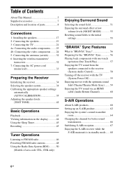
... of parts 8 Connections 1: Installing the speakers 17 2: Connecting the speakers 19 3: Connecting the TV 21 4a: Connecting the audio components.........23 4b: Connecting the video components ........24 5: Connecting the antennas (aerials 32 6: Inserting the wireless transmitter/ transceiver 32 7: Connecting the AC power cord ...with one-touch operation (One-Touch Play 57 Enjoying the TV sound from the speakers connected to the receiver (System Audio Control 58 Turning off the receiver with the TV (System Power Off 59 Enjoying movies with the optimum sound field (Theatre/Theater Mode ...
... of parts 8 Connections 1: Installing the speakers 17 2: Connecting the speakers 19 3: Connecting the TV 21 4a: Connecting the audio components.........23 4b: Connecting the video components ........24 5: Connecting the antennas (aerials 32 6: Inserting the wireless transmitter/ transceiver 32 7: Connecting the AC power cord ...with one-touch operation (One-Touch Play 57 Enjoying the TV sound from the speakers connected to the receiver (System Audio Control 58 Turning off the receiver with the TV (System Power Off 59 Enjoying movies with the optimum sound field (Theatre/Theater Mode ...

Operating Instructions
Page 8
Description and location of parts Front panel 12 3 4 5 67 8 ?/1 qh qg qf qd A ?/1 (on/standby) (page 34, 48, 55) B TONE +/-, TONE MODE (page 81) C INPUT SELECTOR (page 43) D Display (page 9) E Remote sensor Receives signals from remote commander. F DIMMER (page 85) G MASTER VOLUME (page 42, 43) H MUTING (page 43) I VIDEO 2 IN jacks (page 30) qs qa q; 9 J AUTO CAL MIC jack (page 36) K DISPLAY (page 44) L 2CH/A.DIRECT, A.F.D., MOVIE, MUSIC (page 51) M TUNING MODE, TUNING +/-, MEMORY/ENTER (page 46) N INPUT MODE (page 69) O PHONES jack (page 95) P SPEAKERS (page 34) 8GB
Description and location of parts Front panel 12 3 4 5 67 8 ?/1 qh qg qf qd A ?/1 (on/standby) (page 34, 48, 55) B TONE +/-, TONE MODE (page 81) C INPUT SELECTOR (page 43) D Display (page 9) E Remote sensor Receives signals from remote commander. F DIMMER (page 85) G MASTER VOLUME (page 42, 43) H MUTING (page 43) I VIDEO 2 IN jacks (page 30) qs qa q; 9 J AUTO CAL MIC jack (page 36) K DISPLAY (page 44) L 2CH/A.DIRECT, A.F.D., MOVIE, MUSIC (page 51) M TUNING MODE, TUNING +/-, MEMORY/ENTER (page 46) N INPUT MODE (page 69) O PHONES jack (page 95) P SPEAKERS (page 34) 8GB

Operating Instructions
Page 9
...HD High Resolution Audio DTS-HD LBR DTS-HD Low Bit Rate Audio H S-AIR Lights up when TV input is set to "AUTO" and the source signal is activated (page 51). However, these indicators do not light up one of the respective indicators when the receiver is decoding the... connected via an HDMI IN jack (page 24). OPT Lights up one of the respective indicators when the receiver performs Dolby Pro Logic processing. C Input indicators Light up when the audio signal is decoding the corresponding DTSHD format signals. Indicators on the speaker pattern setting. G DTS-HD indicators ...
...HD High Resolution Audio DTS-HD LBR DTS-HD Low Bit Rate Audio H S-AIR Lights up when TV input is set to "AUTO" and the source signal is activated (page 51). However, these indicators do not light up one of the respective indicators when the receiver is decoding the... connected via an HDMI IN jack (page 24). OPT Lights up one of the respective indicators when the receiver performs Dolby Pro Logic processing. C Input indicators Light up when the audio signal is decoding the corresponding DTSHD format signals. Indicators on the speaker pattern setting. G DTS-HD indicators ...

Operating Instructions
Page 10
... letters (L, C, R, etc.) indicate the channels being reproduced. N Tuning indicators Lights up when the receiver tunes in . ST Stereo broadcast O EQ Lights up when the equalizer is set to show how the receiver downmixes or upmixes the source sound (based on the speaker settings). DTS DTS-ES DTS 96/24...the Linear PCM signals. RDS (Models of area code CEL, CEK only) A station that INPUT MODE is activated. L LPCM Lights up when the receiver is tuned in radio stations. Q LFE Lights up when the disc being played back contains an LFE (Low Frequency Effect) channel and the LFE ...
... letters (L, C, R, etc.) indicate the channels being reproduced. N Tuning indicators Lights up when the receiver tunes in . ST Stereo broadcast O EQ Lights up when the equalizer is set to show how the receiver downmixes or upmixes the source sound (based on the speaker settings). DTS DTS-ES DTS 96/24...the Linear PCM signals. RDS (Models of area code CEL, CEK only) A station that INPUT MODE is activated. L LPCM Lights up when the receiver is tuned in radio stations. Q LFE Lights up when the disc being played back contains an LFE (Low Frequency Effect) channel and the LFE ...

Operating Instructions
Page 12
...PR/CR) Y, PB/CB, PR/CR IN/OUT COMPOSITE VIDEO INPUT/ OUTPUT jacks (page 21, 27, 29, 30) High quality image Yellow VIDEO IN/OUT * You can use the supplied remote to operate the receiver and to control the Sony audio/video components that the remote is assigned to operate. F SPEAKERS ...section (page 19) Remote commander You can watch the selected input image when you connect the HDMI TV OUT or MONITOR OUT jack to control non-Sony audio/video components. For details...
...PR/CR) Y, PB/CB, PR/CR IN/OUT COMPOSITE VIDEO INPUT/ OUTPUT jacks (page 21, 27, 29, 30) High quality image Yellow VIDEO IN/OUT * You can use the supplied remote to operate the receiver and to control the Sony audio/video components that the remote is assigned to operate. F SPEAKERS ...section (page 19) Remote commander You can watch the selected input image when you connect the HDMI TV OUT or MONITOR OUT jack to control non-Sony audio/video components. For details...
Operating Instructions
Page 13
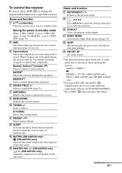
... Adjust the volume level of the input buttons, the receiver turns on the display. R , V/v/B/b Press V/v/B /b to select the settings, then press to control Sony components. Use the tactile dots as references when operating the receiver. - c)Press SHIFT (V) then only press this button....direct tuning mode. U NIGHT MODE Activates the Night Mode function (page 55). number 5, VIDEO 1 -N - To control the receiver Be sure to press AMP (C) to change the remote button function to operate the receiver. MEMORYc) Stores a station during tuner operation. E SOUND FIELD +/- Selects a sound ...
... Adjust the volume level of the input buttons, the receiver turns on the display. R , V/v/B/b Press V/v/B /b to select the settings, then press to control Sony components. Use the tactile dots as references when operating the receiver. - c)Press SHIFT (V) then only press this button....direct tuning mode. U NIGHT MODE Activates the Night Mode function (page 55). number 5, VIDEO 1 -N - To control the receiver Be sure to press AMP (C) to change the remote button function to operate the receiver. MEMORYc) Stores a station during tuner operation. E SOUND FIELD +/- Selects a sound ...

Operating Instructions
Page 14
...to perform a selected operation. Name and function T DISPLAY (RM-AAP049 only) Selects information of AV ?/1 (B) changes automatically each time you connect a Sony TV that is compatible with the THEATER or THEATRE button function (page 59). O TV VOL +/- (RM-AAP049 only) 2 +/- (RM-AAP050 only... Adjusts the TV volume. The function of TV. , (Info, Text reveal) (RM-AAP050 only) Displays information such as references when operating the receiver. - number 5, VIDEO 1 -N - Follow the operation guide to the previous TV menu. M TV INPUT (RM-AAP049 only) (Input select) (RM-AAP050 only) ...
...to perform a selected operation. Name and function T DISPLAY (RM-AAP049 only) Selects information of AV ?/1 (B) changes automatically each time you connect a Sony TV that is compatible with the THEATER or THEATRE button function (page 59). O TV VOL +/- (RM-AAP049 only) 2 +/- (RM-AAP050 only... Adjusts the TV volume. The function of TV. , (Info, Text reveal) (RM-AAP050 only) Displays information such as references when operating the receiver. - number 5, VIDEO 1 -N - Follow the operation guide to the previous TV menu. M TV INPUT (RM-AAP049 only) (Input select) (RM-AAP050 only) ...

Operating Instructions
Page 16
...AAP049 only. For details on the function of batteries. • Do not expose the remote sensor to direct sunlight or lighting apparatuses. number 5, VIDEO 1 -N - e)CD player and MD deck only. Inserting batteries into the remote Insert two R6 (size-AA) batteries in this section may ...Models of area code U2 only) or RM-AAP050 (Models of AV ?/1 (B) changes automatically each time you press ?/1 (A) and AV ?/1 (B) simultaneously, the receiver and connected components will turn off (SYSTEM STANDBY). PRESET +, TV CH + (RM-AAP049 only), PROG + (RM-AAP050 only), c (RM-AAP050 only) b)...
...AAP049 only. For details on the function of batteries. • Do not expose the remote sensor to direct sunlight or lighting apparatuses. number 5, VIDEO 1 -N - e)CD player and MD deck only. Inserting batteries into the remote Insert two R6 (size-AA) batteries in this section may ...Models of area code U2 only) or RM-AAP050 (Models of AV ?/1 (B) changes automatically each time you press ?/1 (A) and AV ?/1 (B) simultaneously, the receiver and connected components will turn off (SYSTEM STANDBY). PRESET +, TV CH + (RM-AAP049 only), PROG + (RM-AAP050 only), c (RM-AAP050 only) b)...
Operating Instructions
Page 17
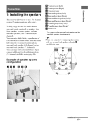
...) or two surround back speakers (7.1 channel). Example of DVD software recorded sound in PLIIz mode (page 52). continued 17GB Connections Connections 1: Installing the speakers This receiver allows you to use the surround back speakers and the front high speakers simultaneously. You can enjoy vertical sound effects if you connect a 7.1 channel speaker...
...) or two surround back speakers (7.1 channel). Example of DVD software recorded sound in PLIIz mode (page 52). continued 17GB Connections Connections 1: Installing the speakers This receiver allows you to use the surround back speakers and the front high speakers simultaneously. You can enjoy vertical sound effects if you connect a 7.1 channel speaker...

Operating Instructions
Page 20
... ONLY) OUT L R IN 1 MONITOR OUT DMPORT DC5V 0.7A MAX VIDEO IN VIDEO IN VIDEO OUT AUDIO IN AUDIO IN AUDIO IN AUDIO IN AUDIO OUT TV DIGITAL (ASSIGNABLE) IN OPTICAL SAT/ CATV IN OPTICAL VIDEO IN VIDEO OUT BD DVD IN IN COAXIAL AUDIO MONITOR IN AUDIO OUT SURROUND BACK/ FRONT HIGH/ BI-AMP/ FRONT B R SA-CD... ASSIGN" to "BI-AMP" in the SPEAKER menu (page 80). Bi-amplifier connection If you are not using the SPEAKERS button on the receiver (page 34). • If you are not touching each other between the SPEAKERS terminals. • After you have an additional front speaker...
... ONLY) OUT L R IN 1 MONITOR OUT DMPORT DC5V 0.7A MAX VIDEO IN VIDEO IN VIDEO OUT AUDIO IN AUDIO IN AUDIO IN AUDIO IN AUDIO OUT TV DIGITAL (ASSIGNABLE) IN OPTICAL SAT/ CATV IN OPTICAL VIDEO IN VIDEO OUT BD DVD IN IN COAXIAL AUDIO MONITOR IN AUDIO OUT SURROUND BACK/ FRONT HIGH/ BI-AMP/ FRONT B R SA-CD... ASSIGN" to "BI-AMP" in the SPEAKER menu (page 80). Bi-amplifier connection If you are not using the SPEAKERS button on the receiver (page 34). • If you are not touching each other between the SPEAKERS terminals. • After you have an additional front speaker...
Operating Instructions
Page 21
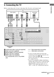
... L SPEAKERS SURROUND R L FRONT A R L A Component video cord (not supplied) B Video cord (not supplied) C Optical digital cord (not supplied) D Audio cord (not supplied) E HDMI cable (not supplied) We recommend that you use a Sony HDMI cable. In this case, set "ARC" to disconnect the AC power cord (mains lead). Be sure to the receiver via HDMI TV OUT...
... L SPEAKERS SURROUND R L FRONT A R L A Component video cord (not supplied) B Video cord (not supplied) C Optical digital cord (not supplied) D Audio cord (not supplied) E HDMI cable (not supplied) We recommend that you use a Sony HDMI cable. In this case, set "ARC" to disconnect the AC power cord (mains lead). Be sure to the receiver via HDMI TV OUT...

Operating Instructions
Page 22
...8226; Do not bend or tie optical digital cords. Unless the power is turned on, neither video nor audio signals will be distorted. Tips • All the digital audio jacks are being output to a TV via the receiver. You may not be able to record, even if you connect recording components. • ... display components such as a TV monitor or a projector to the HDMI TV OUT or MONITOR OUT jack on the receiver. Notes • Be sure to turn on the receiver when the video and audio signals of a playback component are compatible with 32 kHz, 44.1 kHz, 48 kHz, and 96 kHz sampling frequencies....
...8226; Do not bend or tie optical digital cords. Unless the power is turned on, neither video nor audio signals will be distorted. Tips • All the digital audio jacks are being output to a TV via the receiver. You may not be able to record, even if you connect recording components. • ... display components such as a TV monitor or a projector to the HDMI TV OUT or MONITOR OUT jack on the receiver. Notes • Be sure to turn on the receiver when the video and audio signals of a playback component are compatible with 32 kHz, 44.1 kHz, 48 kHz, and 96 kHz sampling frequencies....

Operating Instructions
Page 23
... A Audio cord (not supplied) B Video cord (not supplied) * You can enjoy the images from DMPORT jack DMPORT DC5V 0.7A MAX 1 2 Press and hold both sides of the DIGITAL MEDIA PORT adapter is fragile, be sure to handle with care when placing or moving the receiver. •.../ CB PR / CR COMPONENT VIDEO AUDIO ASSIGNABLE (INPUT ONLY) OUT L R IN 1 MONITOR OUT DMPORT DC5V 0.7A MAX VIDEO IN VIDEO IN VIDEO OUT AUDIO IN AUDIO IN AUDIO IN AUDIO IN AUDIO OUT TV DIGITAL IN OPTICAL SAT/ CATV IN OPTICAL VIDEO IN VIDEO OUT AUDIO MONITOR IN SURRO FRO BI-AM AUDIO OUT SA-CD/CD/CD-R TV...
... A Audio cord (not supplied) B Video cord (not supplied) * You can enjoy the images from DMPORT jack DMPORT DC5V 0.7A MAX 1 2 Press and hold both sides of the DIGITAL MEDIA PORT adapter is fragile, be sure to handle with care when placing or moving the receiver. •.../ CB PR / CR COMPONENT VIDEO AUDIO ASSIGNABLE (INPUT ONLY) OUT L R IN 1 MONITOR OUT DMPORT DC5V 0.7A MAX VIDEO IN VIDEO IN VIDEO OUT AUDIO IN AUDIO IN AUDIO IN AUDIO IN AUDIO OUT TV DIGITAL IN OPTICAL SAT/ CATV IN OPTICAL VIDEO IN VIDEO OUT AUDIO MONITOR IN SURRO FRO BI-AM AUDIO OUT SA-CD/CD/CD-R TV...

Operating Instructions
Page 24
... channels) with a sampling frequency of a playback component are being output to connect all the cords. It is turned on the receiver when the video and audio signals of 192 kHz or less with 32 kHz, 44.1 kHz, 48 kHz, and 96 kHz sampling frequencies. This signal supports...an HDMI connection. • This receiver supports High Bitrate Audio (DTS-HD Master Audio, Dolby TrueHD) and HDMI (Deep Colour (Deep Color), x.v. The receiver equipped with HDMI jacks HDMI is converted. 24GB Unless the power is an interface which transmits video and audio signals in until they have HDMI ...
... channels) with a sampling frequency of a playback component are being output to connect all the cords. It is turned on the receiver when the video and audio signals of 192 kHz or less with 32 kHz, 44.1 kHz, 48 kHz, and 96 kHz sampling frequencies. This signal supports...an HDMI connection. • This receiver supports High Bitrate Audio (DTS-HD Master Audio, Dolby TrueHD) and HDMI (Deep Colour (Deep Color), x.v. The receiver equipped with HDMI jacks HDMI is converted. 24GB Unless the power is an interface which transmits video and audio signals in until they have HDMI ...

Operating Instructions
Page 25
..." (page 85). • You can also rename the HDMI input so that it can use a Sony HDMI cable. continued 25GB Audio/video signals TV, etc.* * See page 21 for the audio connection of the HDMI 1-4 input button on the receiver's display. For details, see "Naming inputs" (page 44). Notes • Be sure to change the...
..." (page 85). • You can also rename the HDMI input so that it can use a Sony HDMI cable. continued 25GB Audio/video signals TV, etc.* * See page 21 for the audio connection of the HDMI 1-4 input button on the receiver's display. For details, see "Naming inputs" (page 44). Notes • Be sure to change the...

Operating Instructions
Page 26
... cable, 1080p or Deep Colour (Deep Color) images may not be displayed properly. • Sony recommends that you want to listen to the sound from the TV speaker, set "PASS THRU" to "OFF", video and audio signals will not output from the TV speaker. • DSD signals of Super... TV through this case, check the specification of the connected component. • Be sure to turn on the receiver when video and audio signals of a playback component are not output. • Audio signals (sampling frequency, bit length, etc.) transmitted from an HDMI jack may need certain settings be made before ...
... cable, 1080p or Deep Colour (Deep Color) images may not be displayed properly. • Sony recommends that you want to listen to the sound from the TV speaker, set "PASS THRU" to "OFF", video and audio signals will not output from the TV speaker. • DSD signals of Super... TV through this case, check the specification of the connected component. • Be sure to turn on the receiver when video and audio signals of a playback component are not output. • Audio signals (sampling frequency, bit length, etc.) transmitted from an HDMI jack may need certain settings be made before ...

Operating Instructions
Page 28
...control other components, be displayed on the receiver's display. RM-AAP049: DVD player - Connecting a DVD player, DVD recorder The following illustration shows how to the operating instructions supplied with an OPTICAL jack, set the digital audio output setting on the DVD player or ...OUT L R IN 1 MONITOR OUT DMPORT DC5V 0.7A MAX VIDEO IN VIDEO IN VIDEO OUT AUDIO IN AUDIO IN AUDIO IN AUDIO IN AUDIO OUT TV DIGITAL (ASSIGNABLE) IN OPTICAL SAT/ CATV IN OPTICAL VIDEO IN VIDEO OUT BD DVD IN IN COAXIAL AUDIO MONITOR IN AUDIO OUT SURROUND BACK/ FRONT HIGH/ BI-AMP/ FRONT B R...
...control other components, be displayed on the receiver's display. RM-AAP049: DVD player - Connecting a DVD player, DVD recorder The following illustration shows how to the operating instructions supplied with an OPTICAL jack, set the digital audio output setting on the DVD player or ...OUT L R IN 1 MONITOR OUT DMPORT DC5V 0.7A MAX VIDEO IN VIDEO IN VIDEO OUT AUDIO IN AUDIO IN AUDIO IN AUDIO IN AUDIO OUT TV DIGITAL (ASSIGNABLE) IN OPTICAL SAT/ CATV IN OPTICAL VIDEO IN VIDEO OUT BD DVD IN IN COAXIAL AUDIO MONITOR IN AUDIO OUT SURROUND BACK/ FRONT HIGH/ BI-AMP/ FRONT B R...


