
Limited Warranty (U.S. Only)
Page 1
..., misuse, abuse, negligence, commercial use, or modification of a service problem, or for one (1) year. This warranty does not cover damage due to improper operation or maintenance, connection to improper voltage supply, or attempted repair by Sony to any part of the Product, including the antenna. This warranty does not cover customer instruction, installation, set up adjustments or signal reception problems. This warranty does not cover...
..., misuse, abuse, negligence, commercial use, or modification of a service problem, or for one (1) year. This warranty does not cover damage due to improper operation or maintenance, connection to improper voltage supply, or attempted repair by Sony to any part of the Product, including the antenna. This warranty does not cover customer instruction, installation, set up adjustments or signal reception problems. This warranty does not cover...

Service Manual
Page 1
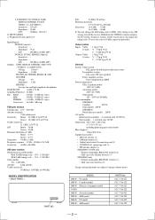
... W a) Depending on next page - rated 110 W (STR-DB930) and 100 W (STR-DB830) per channel minimum RMS power, with sound field, equalizer, and bass boost bypassed) Inputs(Analog) PHONO : Sensitivity : 2.5 mV Impedance : 50 kΩ S/Nb) : 86 dB(A, 2.5 mVc)) - SPECIFICATIONS AUDIO POWER SPECIFICATIONS POWER OUTPUT AND TOTAL HARMONIC DISTORTION : With 8 Ω loads, both channels driven, from Dolby Laboratories Licensing Corporation. Continued on the sound field settings and the source, there may be no more than...
... W a) Depending on next page - rated 110 W (STR-DB930) and 100 W (STR-DB830) per channel minimum RMS power, with sound field, equalizer, and bass boost bypassed) Inputs(Analog) PHONO : Sensitivity : 2.5 mV Impedance : 50 kΩ S/Nb) : 86 dB(A, 2.5 mVc)) - SPECIFICATIONS AUDIO POWER SPECIFICATIONS POWER OUTPUT AND TOTAL HARMONIC DISTORTION : With 8 Ω loads, both channels driven, from Dolby Laboratories Licensing Corporation. Continued on the sound field settings and the source, there may be no more than...
Service Manual
Page 2
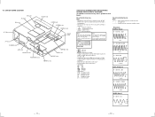
...; FM wire antenna (1) • AM loop antenna (1) • Audio/video/control S connecting cord (1) • CONTROL A1 connecting cord (1) • FM antenna adapter (1) STR-DB930, V929X only • Remote commander RM-LJ302 (remote) (1) • LR6 (size-AA) alkaline batteries (3) STR-DB830 only • Remote commander RM-PP402 (remote) (1) • LR6 (size-AA) batteries (2) Design and specifications are subject to 10 kHz, repeat the procedure. Hold down the TUNING + button and press the 1/u button. Impedance : - PART NO. To reset the...
...; FM wire antenna (1) • AM loop antenna (1) • Audio/video/control S connecting cord (1) • CONTROL A1 connecting cord (1) • FM antenna adapter (1) STR-DB930, V929X only • Remote commander RM-LJ302 (remote) (1) • LR6 (size-AA) alkaline batteries (3) STR-DB830 only • Remote commander RM-PP402 (remote) (1) • LR6 (size-AA) batteries (2) Design and specifications are subject to 10 kHz, repeat the procedure. Hold down the TUNING + button and press the 1/u button. Impedance : - PART NO. To reset the...
Service Manual
Page 3
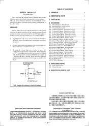
...ÉS PAR SONY. - 3 - Schematic Diagram Speaker Switch Section 29 4-13. Check leakage as the Simpson 229 or RCA WT-540A. Schematic Diagram Rear AMP Section 33 4-15. A. A) To Exposed Metal Parts on Set 0.15µF 1.5kΩ AC voltmeter (0.75V) TABLE OF CONTENTS 1. TEST MODE 6 4. Printed Wiring Board Video Section 39 4-18. ELECTRICAL PARTS LIST 66 Earth Ground Fig. SAFETY-RELATED COMPONENT WARNING!! Schematic Diagram Digital Section(3/3 17 4-7. Schematic Diagram Display Section 25...
...ÉS PAR SONY. - 3 - Schematic Diagram Speaker Switch Section 29 4-13. Check leakage as the Simpson 229 or RCA WT-540A. Schematic Diagram Rear AMP Section 33 4-15. A. A) To Exposed Metal Parts on Set 0.15µF 1.5kΩ AC voltmeter (0.75V) TABLE OF CONTENTS 1. TEST MODE 6 4. Printed Wiring Board Video Section 39 4-18. ELECTRICAL PARTS LIST 66 Earth Ground Fig. SAFETY-RELATED COMPONENT WARNING!! Schematic Diagram Digital Section(3/3 17 4-7. Schematic Diagram Display Section 25...
Service Manual
Page 4
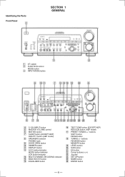
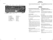
...the Parts Front Panel SECTION 1 GENERAL 1 1/u switch 2 FUNCTION control MODE button 3 INPUT MODE button 4 5.1CH INPUT button 5 MASTER VOLUME control 6 MUTING button 7 SLEEP button (EXCEPT AEP) RDS PTY button (AEP model) 8 SPEAKERS selector PHONES jack 9 DOOR OPEN button 0 DIMMER button !¡ DISPLAY button !™ A.F.D button/indicator MODE button/indicator 2CH button/indicator !£ MULTI CHANNEL DECODING indicator !¢ BASS BOOST button !∞ EQUALIZER button !§ TEST TONE button (EXCEPT AEP) RDS EON button (AEP model) !¶ PRESET TUNING +/- buttons SHIFT button FM...
...the Parts Front Panel SECTION 1 GENERAL 1 1/u switch 2 FUNCTION control MODE button 3 INPUT MODE button 4 5.1CH INPUT button 5 MASTER VOLUME control 6 MUTING button 7 SLEEP button (EXCEPT AEP) RDS PTY button (AEP model) 8 SPEAKERS selector PHONES jack 9 DOOR OPEN button 0 DIMMER button !¡ DISPLAY button !™ A.F.D button/indicator MODE button/indicator 2CH button/indicator !£ MULTI CHANNEL DECODING indicator !¢ BASS BOOST button !∞ EQUALIZER button !§ TEST TONE button (EXCEPT AEP) RDS EON button (AEP model) !¶ PRESET TUNING +/- buttons SHIFT button FM...
Service Manual
Page 5
...; 0 Select the desired step. 1 ANTENNA 2 SIGNAL GND 3 DIGITAL 4 5-1 CH INPUT 5 SPEAKERS (FRONT) 6 SPEAKERS (REAR) 7 SPEAKERS (CENTER) 8 PREOUT 9 IMPEDANCE SELECTOR !º AC OUTLET !¡ AC power cord !™ S-LINK !£ 2ND AUDIO OUT !¢ VIDEO 1 !∞ VIDEO 2 !§ DVD/LD !¶ TV/SAT !• TAPE !ª MD/DAT @º CD @¡ PHONO @™ MONITOR FACTORY SET MODE * All preset contents are cleared when this mode is turned off the main power. ALL CLEAR MODE * All preset contents are reset to the default setting...
...; 0 Select the desired step. 1 ANTENNA 2 SIGNAL GND 3 DIGITAL 4 5-1 CH INPUT 5 SPEAKERS (FRONT) 6 SPEAKERS (REAR) 7 SPEAKERS (CENTER) 8 PREOUT 9 IMPEDANCE SELECTOR !º AC OUTLET !¡ AC power cord !™ S-LINK !£ 2ND AUDIO OUT !¢ VIDEO 1 !∞ VIDEO 2 !§ DVD/LD !¶ TV/SAT !• TAPE !ª MD/DAT @º CD @¡ PHONO @™ MONITOR FACTORY SET MODE * All preset contents are cleared when this mode is turned off the main power. ALL CLEAR MODE * All preset contents are reset to the default setting...
Service Manual
Page 6
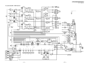
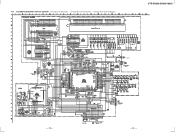
... LAT • RCH is omitted • Signal Path : FM : PHONO : CD : DVD D1201 PRE RY AC MUTE PROTECTOR HP RY SP/A RY SP/B RY C RY CENTER RY WOOFER REAR SP RY U DATA U CLOCK U MREQ U SREQ U REST RESET RY POWER D STOP SOT0 SIN1 MD2 MD0 - 7 - - 8 - BLOCK DIAGRAM MAIN SECTION SECTION 4 DIAGRAMS TM301 ANTENNA FM 75Ω AM TUNER UNIT FM AM ANT LEVEL 6 FM DET 9 L OUT 10 RDS 2 4 IC1 16...
... LAT • RCH is omitted • Signal Path : FM : PHONO : CD : DVD D1201 PRE RY AC MUTE PROTECTOR HP RY SP/A RY SP/B RY C RY CENTER RY WOOFER REAR SP RY U DATA U CLOCK U MREQ U SREQ U REST RESET RY POWER D STOP SOT0 SIN1 MD2 MD0 - 7 - - 8 - BLOCK DIAGRAM MAIN SECTION SECTION 4 DIAGRAMS TM301 ANTENNA FM 75Ω AM TUNER UNIT FM AM ANT LEVEL 6 FM DET 9 L OUT 10 RDS 2 4 IC1 16...
Service Manual
Page 7
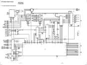
... 12345 PHONO TUNER CD MD/DAT TAPE JOG UP JOG DOWN USREQ FUNCTION UP FUNCTION DOWN UDATA UCLOCK UMREQ URESET MD0 MD2 SINO SOTO MODE CONTROL IC102 KEY INPUT 4 KEY INPUT 5 KEY INPUT 3 KEY INPUT 2 KEY INPUT 1 MBUS TV MBUS STA OUT MBUS VIDEO 1 MBUS DVD 95 ...Signal Path :FM :CD C TM701 S(L) SURROUND SPEAKER S(R) L JJ101 SUB WOOFER R L REAR R L FRONT R JJ102 CENTER +5V PRE OUT +15V -15V +32V 1 +5V REG 3 Q801 +32V REG IC401 3 +15V REG 1 IC402 3 -15V REG 2 D801 S801 IMPEDANCE SELECTOR 48 T901 F801 D1209 Q101 +VDD -VDD SWITCH Q613 +24V F802 D802-805 F803 F804 DIGITAL...
... 12345 PHONO TUNER CD MD/DAT TAPE JOG UP JOG DOWN USREQ FUNCTION UP FUNCTION DOWN UDATA UCLOCK UMREQ URESET MD0 MD2 SINO SOTO MODE CONTROL IC102 KEY INPUT 4 KEY INPUT 5 KEY INPUT 3 KEY INPUT 2 KEY INPUT 1 MBUS TV MBUS STA OUT MBUS VIDEO 1 MBUS DVD 95 ...Signal Path :FM :CD C TM701 S(L) SURROUND SPEAKER S(R) L JJ101 SUB WOOFER R L REAR R L FRONT R JJ102 CENTER +5V PRE OUT +15V -15V +32V 1 +5V REG 3 Q801 +32V REG IC401 3 +15V REG 1 IC402 3 -15V REG 2 D801 S801 IMPEDANCE SELECTOR 48 T901 F801 D1209 Q101 +VDD -VDD SWITCH Q613 +24V F802 D802-805 F803 F804 DIGITAL...
Service Manual
Page 8
... board SP-SW board SP SW board VIDEO board S-VIDEO board DIGITAL board TUNER board HP board F-VIDEO board LED board DISPLAY board REAR AMP board JOINT(Q) board MAIN board VOLUME board ROTARY board THIS NOTE IS COMMON FOR PRINTED WIRING BOARDS AND SCHEMATIC DIAGRAMS. (In addition to ground under no-signal (detuned) conditions. No mark : FM • Voltages are taken with respect to...
... board SP-SW board SP SW board VIDEO board S-VIDEO board DIGITAL board TUNER board HP board F-VIDEO board LED board DISPLAY board REAR AMP board JOINT(Q) board MAIN board VOLUME board ROTARY board THIS NOTE IS COMMON FOR PRINTED WIRING BOARDS AND SCHEMATIC DIAGRAMS. (In addition to ground under no-signal (detuned) conditions. No mark : FM • Voltages are taken with respect to...
Service Manual
Page 15
4-10. TO LED BOARD (PAGE 29) - 26 - SCHEMATIC DIAGRAM DISPLAY SECTION • See page 12 for Waveforms. • See page 56 for IC Pin Functions. • See page 60 for IC Block Diagrams. STR-DB830/DB930/V929X SWITCH - 25 -
4-10. TO LED BOARD (PAGE 29) - 26 - SCHEMATIC DIAGRAM DISPLAY SECTION • See page 12 for Waveforms. • See page 56 for IC Pin Functions. • See page 60 for IC Block Diagrams. STR-DB830/DB930/V929X SWITCH - 25 -
Service Manual
Page 27
... signal Open drain HCIF chip select HCIF address input HCIF data input/output Ground +3.3V HCIF data input/output Reset input "L": active Test data output Ground External RAM data input/output Ground +3.3V External RAM data input/output Test data input "L" = normal "H" = test (Connected to ground) Ground +3.3V External RAM data input/output Ground External RAM data input/output External RAM output ...CAS O 74 XWE O 75 RAS O 76 - 80 EA0 - ED31 I 27 - 30 FGP0 - SOD O 6, 7 ECJ0, ECJ1 I 8 - 4-22. IC PIN FUNCTION DESCRIPTION IC1401 CXD2712R AUDIO DSP(DIGITAL BOARD) Pin No.
... signal Open drain HCIF chip select HCIF address input HCIF data input/output Ground +3.3V HCIF data input/output Reset input "L": active Test data output Ground External RAM data input/output Ground +3.3V External RAM data input/output Test data input "L" = normal "H" = test (Connected to ground) Ground +3.3V External RAM data input/output Ground External RAM data input/output External RAM output ...CAS O 74 XWE O 75 RAS O 76 - 80 EA0 - ED31 I 27 - 30 FGP0 - SOD O 6, 7 ECJ0, ECJ1 I 8 - 4-22. IC PIN FUNCTION DESCRIPTION IC1401 CXD2712R AUDIO DSP(DIGITAL BOARD) Pin No.
Service Manual
Page 29
... 30 CDTI O To AK4526A data input 31 CDTO I Not used (Connected to ground) 34 C - Ground (Connected to ground) 42 AVCC - Not used (Connected to ground) 38 DVCC - Digital Ground (Connected to ground) 40 N.C O Not used (Connected to ground) 37 N.C I To AK4526A data output 32 PD O To AK4526A reset 33 VSS - Analog power supply +5 V 43 AVR+ - Ground (Connected to ground) 41 N.C - Power supply +5 V 44 AVR- - Power supply +5 V 9 SIN0 I ZERO data...
... 30 CDTI O To AK4526A data input 31 CDTO I Not used (Connected to ground) 34 C - Ground (Connected to ground) 42 AVCC - Not used (Connected to ground) 38 DVCC - Digital Ground (Connected to ground) 40 N.C O Not used (Connected to ground) 37 N.C I To AK4526A data output 32 PD O To AK4526A reset 33 VSS - Analog power supply +5 V 43 AVR+ - Ground (Connected to ground) 41 N.C - Power supply +5 V 44 AVR- - Power supply +5 V 9 SIN0 I ZERO data...
Service Manual
Page 30
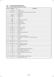
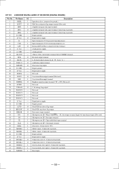
... used (Connected to ground) Not used (Connected to ground) Ground (Connected to ground) Not used (Connected to ground) TH Protector input Protector input AC power check Not used (Connected to ground) Not used (Connected to ground) Not used (Connected to ground) Not used (Connected to ground) Video select SW4 Not used Not used Video select SW3 Video select SW2 Video select SW1 Digital function Tape NO/YES input I VIDEO3 NO/ YES input DTS NO/ YES input Power amp mute ON/OFF output 96K NO/YES input Tuner muting Surround muting (Connected to ground) Hardware standby (Connected...
... used (Connected to ground) Not used (Connected to ground) Ground (Connected to ground) Not used (Connected to ground) TH Protector input Protector input AC power check Not used (Connected to ground) Not used (Connected to ground) Not used (Connected to ground) Not used (Connected to ground) Video select SW4 Not used Not used Video select SW3 Video select SW2 Video select SW1 Digital function Tape NO/YES input I VIDEO3 NO/ YES input DTS NO/ YES input Power amp mute ON/OFF output 96K NO/YES input Tuner muting Surround muting (Connected to ground) Hardware standby (Connected...

Service Manual
Page 31
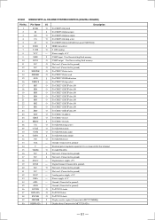
Center speaker relay Rear speaker relay Sub Woofer relay Head phone relay Power relay Analog/digital selection Digital input select B Digital input select A Direct pass relay To LC89055 clock To LC89055 latch To LC89055 data To LC89055 C-bit Error output to LC89055 Non PCM sync detect flag LC89055 Non PCM data detect flag LC89056 C-bit change flag LC89055 Xtal status Frag LC89055 Ground (Connected to ground) Not used (Connected to ground) Description - 53 - Pin Name I/O 101 RY...
Center speaker relay Rear speaker relay Sub Woofer relay Head phone relay Power relay Analog/digital selection Digital input select B Digital input select A Direct pass relay To LC89055 clock To LC89055 latch To LC89055 data To LC89055 C-bit Error output to LC89055 Non PCM sync detect flag LC89055 Non PCM data detect flag LC89056 C-bit change flag LC89055 Xtal status Frag LC89055 Ground (Connected to ground) Not used (Connected to ground) Description - 53 - Pin Name I/O 101 RY...
Service Manual
Page 32
... selected "L": External clock source selected "NC": If pin is floating then test mode is powered-down and the control registers are reset to default state. ORed with serial control register if P/S = "L" (Connected to ground) Audio data master/slave mode select pin "L": slave mode, "H": master mode (Connected to ground) Audio serial data clock pin Input/output channel clock pin DAC1 audio serial data input pin DAC2 audio serial data input pin DAC3 audio serial data input pin Audio serial data output pin AUX audio...
... selected "L": External clock source selected "NC": If pin is floating then test mode is powered-down and the control registers are reset to default state. ORed with serial control register if P/S = "L" (Connected to ground) Audio data master/slave mode select pin "L": slave mode, "H": master mode (Connected to ground) Audio serial data clock pin Input/output channel clock pin DAC1 audio serial data input pin DAC2 audio serial data input pin DAC3 audio serial data input pin Audio serial data output pin AUX audio...

Service Manual
Page 34
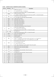
... DISPLAY CONTROL(DISPLAY BOARD) Pin No. TUNER display data output to this terminal. Not used (Connected to Ground) Not used (Connected to Ground) Not used (Connected to Ground) Not used (Connected to Ground) Not used (Connected to Ground) Not used (Connected to Ground) Analog power supply +5 V AVRH (Connected to power supply +5 V) SVRL (Connected to Ground) Ground (Connected to Ground) Key input 1 Key input 2 Key input 3 Key input 4 Ground (Connected to Ground) Key input 5 Not used (Pull up) Not used (Pull up) RDS signal input...
... DISPLAY CONTROL(DISPLAY BOARD) Pin No. TUNER display data output to this terminal. Not used (Connected to Ground) Not used (Connected to Ground) Not used (Connected to Ground) Not used (Connected to Ground) Not used (Connected to Ground) Not used (Connected to Ground) Analog power supply +5 V AVRH (Connected to power supply +5 V) SVRL (Connected to Ground) Ground (Connected to Ground) Key input 1 Key input 2 Key input 3 Key input 4 Ground (Connected to Ground) Key input 5 Not used (Pull up) Not used (Pull up) RDS signal input...
Service Manual
Page 35
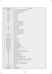
... (Connected to MB90573 DISPMR) Master data output (Connected to MB90573 DISP DATA) Master clock output (Connected to MB90573 DISPCLK) Audio bus input Speaker A signal input. Virsion input. Virsion input. Function encoder down output Not used . (Connected to Ground) Learning microprocessor latch output. Reset. Pin No. Reset (Display MCU) Rotary encoder input. Virsion input. LED data input. Function encoder up output Volume down input. DVD input from MBUS. Virsion output. Description MD 2 Hardware STANDBY input RDS clock input RDS data input Volume up input...
... (Connected to MB90573 DISPMR) Master data output (Connected to MB90573 DISP DATA) Master clock output (Connected to MB90573 DISPCLK) Audio bus input Speaker A signal input. Virsion input. Virsion input. Function encoder down output Not used . (Connected to Ground) Learning microprocessor latch output. Reset. Pin No. Reset (Display MCU) Rotary encoder input. Virsion input. LED data input. Function encoder up output Volume down input. DVD input from MBUS. Virsion output. Description MD 2 Hardware STANDBY input RDS clock input RDS data input Volume up input...
Service Manual
Page 36
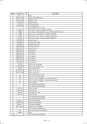
... used.) 24 AUDIO - Not used. 21 XOUT O Crystal oscillator output terminal (Not used.) 22 XIN I /F RECEIVER (DIGITAL BOARD) Pin No. Digital ground 32 AUTO O Non PCM data detect flag output. 33 BPSYNC O Non PCM sync detect flag output. 34 ERROR O Error mute output terminal 35 DO O Microprocessor I Amplifier integrate data input terminal (Connecting to ground.) 41 MODE1 I Reset input. - 58 - Pin Name I/O Description 1 DISEL I Input data select. (connected to ground) 5 DIN2 I /F. Not used ) 3 DIN0 I Amplifier integrate data input...
... used.) 24 AUDIO - Not used. 21 XOUT O Crystal oscillator output terminal (Not used.) 22 XIN I /F RECEIVER (DIGITAL BOARD) Pin No. Digital ground 32 AUTO O Non PCM data detect flag output. 33 BPSYNC O Non PCM sync detect flag output. 34 ERROR O Error mute output terminal 35 DO O Microprocessor I Amplifier integrate data input terminal (Connecting to ground.) 41 MODE1 I Reset input. - 58 - Pin Name I/O Description 1 DISEL I Input data select. (connected to ground) 5 DIN2 I /F. Not used ) 3 DIN0 I Amplifier integrate data input...

Service Manual
Page 44
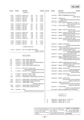
... 1SS352-TPH3 - 66 - When indicating parts by mark ! are in the diagrams or the components used on the set. • -XX, -X mean standardized parts, so they are seldom required for safety. sont critiques pour la sécurité. Ref. No. Part No. Some delay should be different from the original one....1-571-309-11 SWITCH (INPEDANCE SELECTOR * 1-673-353-11 AC BOARD ******** 1-533-217-41 HOLDER, FUSE < CAPACITOR > C901 1-163-037-11 CERAMIC CHIP 0.022uF 10% 25V C902 1-163-037-11 CERAMIC CHIP 0.022uF 10% 25V C905 1-126-767-11 ELECT 1000uF 20% 16V < JACK > ! CNJ901 1-...
... 1SS352-TPH3 - 66 - When indicating parts by mark ! are in the diagrams or the components used on the set. • -XX, -X mean standardized parts, so they are seldom required for safety. sont critiques pour la sécurité. Ref. No. Part No. Some delay should be different from the original one....1-571-309-11 SWITCH (INPEDANCE SELECTOR * 1-673-353-11 AC BOARD ******** 1-533-217-41 HOLDER, FUSE < CAPACITOR > C901 1-163-037-11 CERAMIC CHIP 0.022uF 10% 25V C902 1-163-037-11 CERAMIC CHIP 0.022uF 10% 25V C905 1-126-767-11 ELECT 1000uF 20% 16V < JACK > ! CNJ901 1-...
Service Manual
Page 63
...-11 ACCESSORIES & PACKING MATERIALS REMOTE COMMANDER (RM-LJ302) (DB930,V929X) ANTENNA (FM) (DB830:AEP/DB930:AEP,MY,SP,AUS,V929X) ANTENNA (LOOP) CORD, CONNECTION(CONTROL A1 CABLE 1P) (DB830:US/DB930:US,CND) CORD, CONNECTION(AVC CABLE 4P) (DB830:US/DB930:US,CND) 3-866-295-11 3-866-295-21 3-866-295-31 3-866-295-41 MANUAL, INSTRUCTION (RM-LJ302) (ENGLISH)(DB930,V929X) MANUAL, INSTRUCTION (RM-LJ302) (FRENCH,SPANISH...
...-11 ACCESSORIES & PACKING MATERIALS REMOTE COMMANDER (RM-LJ302) (DB930,V929X) ANTENNA (FM) (DB830:AEP/DB930:AEP,MY,SP,AUS,V929X) ANTENNA (LOOP) CORD, CONNECTION(CONTROL A1 CABLE 1P) (DB830:US/DB930:US,CND) CORD, CONNECTION(AVC CABLE 4P) (DB830:US/DB930:US,CND) 3-866-295-11 3-866-295-21 3-866-295-31 3-866-295-41 MANUAL, INSTRUCTION (RM-LJ302) (ENGLISH)(DB930,V929X) MANUAL, INSTRUCTION (RM-LJ302) (FRENCH,SPANISH...


