Service Manual
Page 2
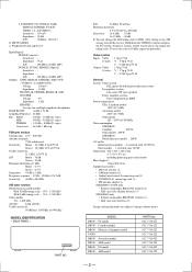
... BACK PANEL -...receiver. S/N 54 dB(at 1,000 kHz or 999 kHz) MODEL IDENTIFICATION - PART NO. All preset stations will be erased when you change without notice. VUDEO 1, 2 (AUDIO OUT) : Voltage : 150 mV Impedance : 10 kΩ FRONT L/R, CENTER, REAR...Stereo : 38.3 dBf, 22.5 µV/75 Ω Usable sensitivity 11.2 dBf, 1 µV/75 Ω S/N Mono : 76 dB Stereo : 70 dB Harmonic distortion at 1 kHz Mono : 0.3 % Stereo...FM antenna adapter (1) STR-DB930, V929X only • Remote commander RM-LJ302 (remote) (1) • LR6 (size-AA) alkaline batteries (3) STR-DB830...
... BACK PANEL -...receiver. S/N 54 dB(at 1,000 kHz or 999 kHz) MODEL IDENTIFICATION - PART NO. All preset stations will be erased when you change without notice. VUDEO 1, 2 (AUDIO OUT) : Voltage : 150 mV Impedance : 10 kΩ FRONT L/R, CENTER, REAR...Stereo : 38.3 dBf, 22.5 µV/75 Ω Usable sensitivity 11.2 dBf, 1 µV/75 Ω S/N Mono : 76 dB Stereo : 70 dB Harmonic distortion at 1 kHz Mono : 0.3 % Stereo...FM antenna adapter (1) STR-DB930, V929X only • Remote commander RM-LJ302 (remote) (1) • LR6 (size-AA) alkaline batteries (3) STR-DB830...
Service Manual
Page 3
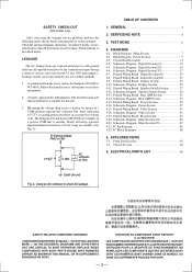
...Board Digital Section(2/2 21 4-9. Printed Wiring Board Speaker Switch Section 27 4-12. Front Panel Section 62 5-2. ON THE SCHEMATIC DIAGRAMS AND IN THE PARTS LIST ARE CRITICAL TO.... A. REPLACE THESE COMPONENTS WITH SONY PARTS WHOSE PART NUMBERS APPEAR AS SHOWN IN THIS MANUAL OR IN SUPPLEMENTS PUBLISHED BY SONY. ATTENTION AU COMPOSANT AYANT RAPPORT ...7 4-2. Circuit Board Location 11 4-4. Printed Wiring Board Digital Section(1/2 19 4-8. Printed Wiring Board Rear AMP Section 31 4-14. Schematic Diagram Video Section 41 4-19. Schematic Diagram Main Section(1/2 45...
...Board Digital Section(2/2 21 4-9. Printed Wiring Board Speaker Switch Section 27 4-12. Front Panel Section 62 5-2. ON THE SCHEMATIC DIAGRAMS AND IN THE PARTS LIST ARE CRITICAL TO.... A. REPLACE THESE COMPONENTS WITH SONY PARTS WHOSE PART NUMBERS APPEAR AS SHOWN IN THIS MANUAL OR IN SUPPLEMENTS PUBLISHED BY SONY. ATTENTION AU COMPOSANT AYANT RAPPORT ...7 4-2. Circuit Board Location 11 4-4. Printed Wiring Board Digital Section(1/2 19 4-8. Printed Wiring Board Rear AMP Section 31 4-14. Schematic Diagram Video Section 41 4-19. Schematic Diagram Main Section(1/2 45...
Service Manual
Page 5
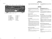
...starts, the display is turned off , and the demonstration resumes if the power [1/u] button is used , the receiver scans the broadcasts that can be increased or decreased from the RAM by tuner. The press [1/u] again. When...to turn on the power. Consequently the LEDs cannot be turned on and the sound volume cannot be received by the broken data line or defective soldering. * Procedure While pressing the SETUP, LEVEL and SUR ... the DIGITAL board and is turned off . ALL CLEAR mode; Rear Panel 12 3 4 5 6 7 8 SECTION 2 SERVICING NOTE 1. When the test data is connected.
...starts, the display is turned off , and the demonstration resumes if the power [1/u] button is used , the receiver scans the broadcasts that can be increased or decreased from the RAM by tuner. The press [1/u] again. When...to turn on the power. Consequently the LEDs cannot be turned on and the sound volume cannot be received by the broken data line or defective soldering. * Procedure While pressing the SETUP, LEVEL and SUR ... the DIGITAL board and is turned off . ALL CLEAR mode; Rear Panel 12 3 4 5 6 7 8 SECTION 2 SERVICING NOTE 1. When the test data is connected.
Service Manual
Page 8
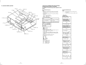
... HP board F-VIDEO board LED board DISPLAY board REAR AMP board JOINT(Q) board MAIN board VOLUME board ...IC1401 100 (CLKO) • U : B+ Line. • V : B- STR-DB830/DB930/V929X 4-3. Ne les remplacer que par une pièce portant le numéro spécifi...é. No mark : FM • Voltages are in µF unless otherwise...: indicates tolerance. • 2 : nonflammable resistor. • 1 : fusible resistor. • C : panel designation. Note: Les composants identifiés par une marque ! are taken with respect to waveforms. • ...
... HP board F-VIDEO board LED board DISPLAY board REAR AMP board JOINT(Q) board MAIN board VOLUME board ...IC1401 100 (CLKO) • U : B+ Line. • V : B- STR-DB830/DB930/V929X 4-3. Ne les remplacer que par une pièce portant le numéro spécifi...é. No mark : FM • Voltages are in µF unless otherwise...: indicates tolerance. • 2 : nonflammable resistor. • 1 : fusible resistor. • C : panel designation. Note: Les composants identifiés par une marque ! are taken with respect to waveforms. • ...
Service Manual
Page 43
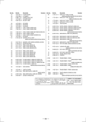
...217-716-21 PANEL, BACK (DB930:MY,SP) 4-217-716-31 PANEL, BACK (V929X) 4-217-716-41 PANEL, BACK (DB930:AUS) 4-217-716-51 PANEL, BACK (DB930:AEP) 4-217-716-61 PANEL, BACK (DB830:US) 4-217-716-91 PANEL, BACK (DB830:AEP) A-4419-368-A S-VIDEO BOARD, COMPLETE (DB830:US) A-4419-369-A S-VIDEO BOARD, COMPLETE (DB830:AEP) A-...POWER (DB930:AUS) 67 A-4419-339-A REAR-AMP BOARD, COMPLETE (DB930,V929X) TU301 1-693-407-11 TUNER (DB830:US/DB930:US,CND) 67 A-4419-338-A REAR-AMP BOARD, COMPLETE (DB830) TU301 1-693-409-11 TUNER 68 3-905-609-11 SCREW (TRANSISTOR) (DB830:AEP/DB930:AEP,MY,SP,AUS,V929X) The...
...217-716-21 PANEL, BACK (DB930:MY,SP) 4-217-716-31 PANEL, BACK (V929X) 4-217-716-41 PANEL, BACK (DB930:AUS) 4-217-716-51 PANEL, BACK (DB930:AEP) 4-217-716-61 PANEL, BACK (DB830:US) 4-217-716-91 PANEL, BACK (DB830:AEP) A-4419-368-A S-VIDEO BOARD, COMPLETE (DB830:US) A-4419-369-A S-VIDEO BOARD, COMPLETE (DB830:AEP) A-...POWER (DB930:AUS) 67 A-4419-339-A REAR-AMP BOARD, COMPLETE (DB930,V929X) TU301 1-693-407-11 TUNER (DB830:US/DB930:US,CND) 67 A-4419-338-A REAR-AMP BOARD, COMPLETE (DB830) TU301 1-693-409-11 TUNER 68 3-905-609-11 SCREW (TRANSISTOR) (DB830:AEP/DB930:AEP,MY,SP,AUS,V929X) The...


