Service Manual
Page 2
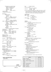
... STR-DB830 North American models : 280 W AC outlets North American models : 2 switched, total 120 W/1A Other models : 1 switched, max 100 W Dimensions 430 × 405 × 160.5 mm (17 × 16 × 63/8 in any AM station, turn off the receiver....S connecting cord (1) • CONTROL A1 connecting cord (1) • FM antenna adapter (1) STR-DB930, V929X only • Remote commander RM-LJ302 (remote) (1) • LR6 (size-AA) alkaline batteries (3) STR-DB830 only • Remote commander RM-PP402 (remote) (1) • LR6 (size-AA) batteries (2) Design and specifications are...
... STR-DB830 North American models : 280 W AC outlets North American models : 2 switched, total 120 W/1A Other models : 1 switched, max 100 W Dimensions 430 × 405 × 160.5 mm (17 × 16 × 63/8 in any AM station, turn off the receiver....S connecting cord (1) • CONTROL A1 connecting cord (1) • FM antenna adapter (1) STR-DB930, V929X only • Remote commander RM-LJ302 (remote) (1) • LR6 (size-AA) alkaline batteries (3) STR-DB830 only • Remote commander RM-PP402 (remote) (1) • LR6 (size-AA) batteries (2) Design and specifications are...
Service Manual
Page 5
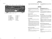
...has started, the power is pressed again. The message S.F Initialize appears and initialization is triggered. When the test data is used , the receiver scans the broadcasts that can be increased or decreased from the RAM by tuner. The message DSP TEST MODE appears. Press the POWER button while...scanning starts by the DSP, the data output must not be equivalent to the original data. VERSION MODE * When this mode is read from the remote control. 2. ALL CLEAR MODE * All preset contents are tested. The machine enters the DEMO mode.DEMO mode: Wait a while, then the demonstration ...
...has started, the power is pressed again. The message S.F Initialize appears and initialization is triggered. When the test data is used , the receiver scans the broadcasts that can be increased or decreased from the RAM by tuner. The message DSP TEST MODE appears. Press the POWER button while...scanning starts by the DSP, the data output must not be equivalent to the original data. VERSION MODE * When this mode is read from the remote control. 2. ALL CLEAR MODE * All preset contents are tested. The machine enters the DEMO mode.DEMO mode: Wait a while, then the demonstration ...
Service Manual
Page 63
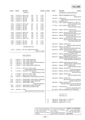
... ! Part No. No. Part No. Description Remarks 1-418-293-11 1-501-594-11 1-501-721-11 1-777-172-11 1-777-560-11 ACCESSORIES & PACKING MATERIALS REMOTE COMMANDER (RM-LJ302) (DB930,V929X) ANTENNA (FM) (DB830:AEP/DB930:AEP,MY,SP,AUS,V929X) ANTENNA (LOOP) CORD, CONNECTION(CONTROL A1 CABLE 1P.../DB930:AEP) 4-981-643-11 COVER BATTERY (FOR RM-LJ302)(DB930,V929X) 8-917-666-90 REMOTE COMMANDER RM-PP402(DB830) HARDWARE LIST #1 7-685-646-79 SCREW +BVTP 3 × 8 TYPE2 IT-3 #2 7-685-885-09 SCREW +BVTT 4 × 16 (S) #3 7-685-853-04 SCREW +BVTT 2 × 6 (S) The components ...
... ! Part No. No. Part No. Description Remarks 1-418-293-11 1-501-594-11 1-501-721-11 1-777-172-11 1-777-560-11 ACCESSORIES & PACKING MATERIALS REMOTE COMMANDER (RM-LJ302) (DB930,V929X) ANTENNA (FM) (DB830:AEP/DB930:AEP,MY,SP,AUS,V929X) ANTENNA (LOOP) CORD, CONNECTION(CONTROL A1 CABLE 1P.../DB930:AEP) 4-981-643-11 COVER BATTERY (FOR RM-LJ302)(DB930,V929X) 8-917-666-90 REMOTE COMMANDER RM-PP402(DB830) HARDWARE LIST #1 7-685-646-79 SCREW +BVTP 3 × 8 TYPE2 IT-3 #2 7-685-885-09 SCREW +BVTT 4 × 16 (S) #3 7-685-853-04 SCREW +BVTT 2 × 6 (S) The components ...


