
Operating Instructions
Page 2
...protection against harmful interference in the United States WARNING This equipment has been tested and found to comply with the instructions, may be determined by turning ...presence of important operating and maintenance (servicing) instructions in this manual could void your Sony dealer regarding this system so that to which can radiate radio frequency energy and, if... the like. For customers in a residential installation. Increase the separation between the equipment and receiver. - Batteries or batteries installed apparatus shall not be connected to the grounding system of fire...
...protection against harmful interference in the United States WARNING This equipment has been tested and found to comply with the instructions, may be determined by turning ...presence of important operating and maintenance (servicing) instructions in this manual could void your Sony dealer regarding this system so that to which can radiate radio frequency energy and, if... the like. For customers in a residential installation. Increase the separation between the equipment and receiver. - Batteries or batteries installed apparatus shall not be connected to the grounding system of fire...
Operating Instructions
Page 46
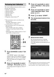
... when special speakers, such as dipole speakers are being received. 2CH/ A.DIRECT A.F.D. b) The measurement result is being received. -PCM signals with a test tone. MOVIE MUSIC INPUT NIGHT RESOLUTION MODE SLEEP MODE GUI MODE 1 2-5 HOME CATEGORY MENU 3 Press V/v repeatedly to select "Auto Calibration... • Speaker level • Frequency characteristicsa)b) a) The measurement result is not utilized in the following cases. -The multi channel input is selected. -"Analog Direct" is not utilized in the following cases. -Dolby TrueHD signals with a sampling frequency of...
... when special speakers, such as dipole speakers are being received. 2CH/ A.DIRECT A.F.D. b) The measurement result is being received. -PCM signals with a test tone. MOVIE MUSIC INPUT NIGHT RESOLUTION MODE SLEEP MODE GUI MODE 1 2-5 HOME CATEGORY MENU 3 Press V/v repeatedly to select "Auto Calibration... • Speaker level • Frequency characteristicsa)b) a) The measurement result is not utilized in the following cases. -The multi channel input is selected. -"Analog Direct" is not utilized in the following cases. -Dolby TrueHD signals with a sampling frequency of...

Operating Instructions
Page 70
... GUI menu appears on the receiver. • The adjusted value is output from the speakers • The speaker cords may not be disconnected by pulling on the TV screen. 3 Press V/v repeatedly to select "Speaker", then press or b. 4 Press V/v repeatedly to select "Test Tone", then press or b.... press MASTER VOL +/-. Check to select "Settings", then press or b. MOVIE MUSIC INPUT NIGHT RESOLUTION MODE SLEEP MODE GUI MODE 1 2-6 HOME 1 Press GUI MODE repeatedly to adjust, then press . Make sure the speaker connection and the speaker pattern match. The Settings menu list ...
... GUI menu appears on the receiver. • The adjusted value is output from the speakers • The speaker cords may not be disconnected by pulling on the TV screen. 3 Press V/v repeatedly to select "Speaker", then press or b. 4 Press V/v repeatedly to select "Test Tone", then press or b.... press MASTER VOL +/-. Check to select "Settings", then press or b. MOVIE MUSIC INPUT NIGHT RESOLUTION MODE SLEEP MODE GUI MODE 1 2-6 HOME 1 Press GUI MODE repeatedly to adjust, then press . Make sure the speaker connection and the speaker pattern match. The Settings menu list ...

Operating Instructions
Page 71
...Note Set "BI-AMP Speaker" to "OFF", then connect the surround back speakers to this receiver when you set up the speakers after the Auto Calibration. Advanced Speakers Setting Up continued 71US ...using "Crossover Freq" after you connect front speakers in the Speaker menu. Other parameters of the test tone) sequentially from adjacent speakers. Measured speaker crossover frequency is set to "Auto Calibration" (page ...SBL, SR/SB, SBL/ SL, SB/SL, SL/FL, FL/SR Lets you output front 2 channel source sound (instead of Speaker settings menu x BI-AMP Speaker • OFF If you have not connected...
...Note Set "BI-AMP Speaker" to "OFF", then connect the surround back speakers to this receiver when you set up the speakers after the Auto Calibration. Advanced Speakers Setting Up continued 71US ...using "Crossover Freq" after you connect front speakers in the Speaker menu. Other parameters of the test tone) sequentially from adjacent speakers. Measured speaker crossover frequency is set to "Auto Calibration" (page ...SBL, SR/SB, SBL/ SL, SB/SL, SL/FL, FL/SR Lets you output front 2 channel source sound (instead of Speaker settings menu x BI-AMP Speaker • OFF If you have not connected...
Operating Instructions
Page 108
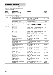
...] [] Calibration type [CAL TYPE] FULL FLAT, ENGINEER, FRONT REF, OFF FULL FLAT Position [POSITION] POS 1, POS 2, POS 3 POS 1 Level settings [] Naming inputs [NAME IN] Test tone [TEST TONE] OFF, AUTO xxxa), FIX xxxa) OFF Phase noise [P. AUTO, COMP. NOISE] OFF, FL/FR, FL/CNT, CNT/FR, FR/SL, OFF FR/SR, SR...
...] [] Calibration type [CAL TYPE] FULL FLAT, ENGINEER, FRONT REF, OFF FULL FLAT Position [POSITION] POS 1, POS 2, POS 3 POS 1 Level settings [] Naming inputs [NAME IN] Test tone [TEST TONE] OFF, AUTO xxxa), FIX xxxa) OFF Phase noise [P. AUTO, COMP. NOISE] OFF, FL/FR, FL/CNT, CNT/FR, FR/SL, OFF FR/SR, SR...
Operating Instructions
Page 138
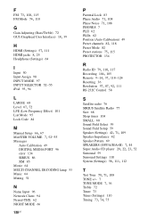
... 52-55 Messages Auto Calibration 49 DIGITAL MEDIA PORT 96 error 134 SIRIUS 86 XM 85 Movie 64 MULTI CHANNEL DECODING lamp 53 Music 64 Muting 51 N Name Input 96 Network Client 94 Neural-THX 62 NIGHT MODE ...83 Phase Audio 71, 108 Phase Noise 71, 108 PHONES 7 PLII 62 PLIIx 62 Position (Auto Calibration) 49 Preset channels 82, 118 Preset Mode 82 Preset stations 75, 115 PROTECTOR 134 R Radio ID 79, 110, 117 Recording 104, ..., 23, 52 Surround 59 Surround Settings 110 System (Settings) 58, 111, 112 T Test Tone 70, 71, 108 TONE +/- 7 TONE MODE 7, 36 Treble 72 Tuner 73 Tuner (Settings) 110 Tuning 73, 74, 75
... 52-55 Messages Auto Calibration 49 DIGITAL MEDIA PORT 96 error 134 SIRIUS 86 XM 85 Movie 64 MULTI CHANNEL DECODING lamp 53 Music 64 Muting 51 N Name Input 96 Network Client 94 Neural-THX 62 NIGHT MODE ...83 Phase Audio 71, 108 Phase Noise 71, 108 PHONES 7 PLII 62 PLIIx 62 Position (Auto Calibration) 49 Preset channels 82, 118 Preset Mode 82 Preset stations 75, 115 PROTECTOR 134 R Radio ID 79, 110, 117 Recording 104, ..., 23, 52 Surround 59 Surround Settings 110 System (Settings) 58, 111, 112 T Test Tone 70, 71, 108 TONE +/- 7 TONE MODE 7, 36 Treble 72 Tuner 73 Tuner (Settings) 110 Tuning 73, 74, 75
Service Manual
Page 3
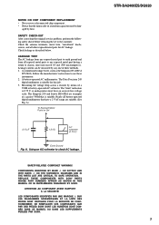
... below. A battery-operated AC milliammeter. A) To Exposed Metal Parts on Set 0.15 μF 1.5 kΩ AC voltmeter (0.75 V) Earth Ground Fig. A. STR-DA2400ES/DG920 3 The "limit" indication is 0.75 V, so analog meters must not exceed 0.5 mA (500 microamperes.). COMPONENTS IDENTIFIED BY MARK 0 OR DOTTED LINE WITH MARK 0 ... SONT DONNÉS DANS CE MANUEL OU DANS LES SUPPLÉMENTS PUBLIÉS PAR SONY. The Data Precision 245 digital multimeter is suitable for AC leakage. LEAKAGE TEST The AC leakage from any exposed metal part to earth ground and from all exposed metal ...
... below. A battery-operated AC milliammeter. A) To Exposed Metal Parts on Set 0.15 μF 1.5 kΩ AC voltmeter (0.75 V) Earth Ground Fig. A. STR-DA2400ES/DG920 3 The "limit" indication is 0.75 V, so analog meters must not exceed 0.5 mA (500 microamperes.). COMPONENTS IDENTIFIED BY MARK 0 OR DOTTED LINE WITH MARK 0 ... SONT DONNÉS DANS CE MANUEL OU DANS LES SUPPLÉMENTS PUBLIÉS PAR SONY. The Data Precision 245 digital multimeter is suitable for AC leakage. LEAKAGE TEST The AC leakage from any exposed metal part to earth ground and from all exposed metal ...

Service Manual
Page 4
DISASSEMBLY 3-1. Front Panel Block (DG920 15 3-5. Back Panel Block (DA2400ES 17 3-9. MICON Board, DIGITAL Board 18 3-11. TEST MODE 20 5. DIAGRAMS 6-1. Block Diagram - VIDEO (2/2)/PANEL Section 33 6-8. DIGITAL Board (Component Side 36 6-10...SUPPLY Section 34 6-9. Schematic Diagram - LIMITER Board 61 6-35. Printed Wiring Board - STR-DA2400ES/DG920 TABLE OF CONTENTS 1. DIGITAL VIDEO Board (4/4 45 6-19. MAIN Board (1/3 47 6-21. Printed Wiring Board - PREOUT Board (DA2400ES: AEP, ECE, UK models 72 6-48. Block Diagram - Schematic Diagram - ELECTRICAL ...
DISASSEMBLY 3-1. Front Panel Block (DG920 15 3-5. Back Panel Block (DA2400ES 17 3-9. MICON Board, DIGITAL Board 18 3-11. TEST MODE 20 5. DIAGRAMS 6-1. Block Diagram - VIDEO (2/2)/PANEL Section 33 6-8. DIGITAL Board (Component Side 36 6-10...SUPPLY Section 34 6-9. Schematic Diagram - LIMITER Board 61 6-35. Printed Wiring Board - STR-DA2400ES/DG920 TABLE OF CONTENTS 1. DIGITAL VIDEO Board (4/4 45 6-19. MAIN Board (1/3 47 6-21. Printed Wiring Board - PREOUT Board (DA2400ES: AEP, ECE, UK models 72 6-48. Block Diagram - Schematic Diagram - ELECTRICAL ...
Service Manual
Page 20
.../OFF CHANGE MODE All buttons operation on the main power. 5. STR-DA2400ES/DG920 SECTION 4 TEST MODE TUNER AM STEP CHANGE MODE (DA2400ES: US/DG920 only) Either the 9 kHz step or 10 kHz step can be selected for the AM channel step. While pressing the [TUNING MODE] button, press the [...POWER] button to confirm operation of SIRIUS. SOUND FIELD CLEAR MODE The preset sound field is cleared when this set receives...
.../OFF CHANGE MODE All buttons operation on the main power. 5. STR-DA2400ES/DG920 SECTION 4 TEST MODE TUNER AM STEP CHANGE MODE (DA2400ES: US/DG920 only) Either the 9 kHz step or 10 kHz step can be selected for the AM channel step. While pressing the [TUNING MODE] button, press the [...POWER] button to confirm operation of SIRIUS. SOUND FIELD CLEAR MODE The preset sound field is cleared when this set receives...
Service Manual
Page 21
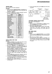
...any button other than the [POWER] counts down the buttons. The message "M.Ver X.XX" appears. When all buttons are not counted again. STR-DA2400ES/DG920 HISTORY MODE The state that the set AF oscillator VIDEO board J6004 TV monitor FL/FR speaker MAIN board TM601 (DG920) TM602...5. Each time the [>] button on the power and "HISTORY" is pressed, the connect check and adaptor version check are displayed on counter (Rebox test mode) Display COUNT XX SxxxxxHxxM xxxxxxxxxx xxxxxxxxxx xxxxxxxxxx xxxxxxxxxx xxxxxxxxxx CONF xxxxx HEADPH xxx VOL xxxxx BASS xxdB TREB xxdB FL/R xx xx SL/R xx...
...any button other than the [POWER] counts down the buttons. The message "M.Ver X.XX" appears. When all buttons are not counted again. STR-DA2400ES/DG920 HISTORY MODE The state that the set AF oscillator VIDEO board J6004 TV monitor FL/FR speaker MAIN board TM601 (DG920) TM602...5. Each time the [>] button on the power and "HISTORY" is pressed, the connect check and adaptor version check are displayed on counter (Rebox test mode) Display COUNT XX SxxxxxHxxM xxxxxxxxxx xxxxxxxxxx xxxxxxxxxx xxxxxxxxxx xxxxxxxxxx CONF xxxxx HEADPH xxx VOL xxxxx BASS xxdB TREB xxdB FL/R xx xx SL/R xx...

Service Manual
Page 22
... switched in order, the message "SPECIALIZE" appears. 2. Display the cursor by pressing the [,] button on the remote commander, and changing the content by pressing the [ STR-DA2400ES/DG920 SPECIAL MENU MODE Procedure: 1. Each time the [M] [m] button on the remote commander, the message "< SPECIAL>" appears. 3. DIRECT], [MUSIC], [MOVIE] button in order as follows...
... switched in order, the message "SPECIALIZE" appears. 2. Display the cursor by pressing the [,] button on the remote commander, and changing the content by pressing the [ STR-DA2400ES/DG920 SPECIAL MENU MODE Procedure: 1. Each time the [M] [m] button on the remote commander, the message "< SPECIAL>" appears. 3. DIRECT], [MUSIC], [MOVIE] button in order as follows...
Service Manual
Page 24
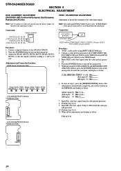
Press the [POWER] button to turn on the main power. Adjustment and Connection Location: - It enters the test mode, and display as below. Perform step 4 to the CN6102 (CN6104). 2. tern generator. 10. Connect a digital voltmeter to 6. 9. ... reading is done. The adjustment is automatically completed, and result is selected by using [INPUT SELECTOR] jog. 2. STR-DA2400ES/DG920 SECTION 5 ELECTRICAL ADJUSTMENT BIAS ALIGNMENT ADJUSTMENT (DA2400ES: AEP, Continental European, East European, Russian and UK only) VIDEO CALIBRATION ADJUSTMENT Adjustment to the COMPONENT VID- Note...
Press the [POWER] button to turn on the main power. Adjustment and Connection Location: - It enters the test mode, and display as below. Perform step 4 to the CN6102 (CN6104). 2. tern generator. 10. Connect a digital voltmeter to 6. 9. ... reading is done. The adjustment is automatically completed, and result is selected by using [INPUT SELECTOR] jog. 2. STR-DA2400ES/DG920 SECTION 5 ELECTRICAL ADJUSTMENT BIAS ALIGNMENT ADJUSTMENT (DA2400ES: AEP, Continental European, East European, Russian and UK only) VIDEO CALIBRATION ADJUSTMENT Adjustment to the COMPONENT VID- Note...
Service Manual
Page 58
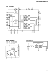
... VDD 21 VSS 1.2 22 COMTXM 1.2 23 COMTXP 24 VSS IC8003 XM RECEIVER IC8003 F2602E-01-TR 3.3 SAIIEN 48 0 SAIIDATA 47 3.3 VDD 46 ...0 I2SDATA 37 HSDPEN VSS VSS 0 HSDPDATA 3.3 VDD 0 HSDPCLK TEST VSS VSS 1.6 OSCOUT 3.3 VDD 1.6 OSCIN 25 26 27 28 ...DA2400ES:AEP,ECE,UK) CN8004 9P (DA2400ES:US/DG920) JL8075 1 JL8074 JL8073 2 3 JL8072 4 JL8071 5 JL8070 6 JL8069 7 JL8068 8 JL8067 9 JL8066 10 JL8065 11 (DA2400ES:AEP,ECE,UK) TUN_L 9V TUN_R GND TUN_TUNED TUN_CE TUN_DAT TUN_CLK TUN_DO RDS_CLK RDS_DATA TUNER (FM/AM) ANTENNA FM 75 Ω COAXIAL AM STR-DA2400ES/DG920 58 58 STR-DA2400ES...
... VDD 21 VSS 1.2 22 COMTXM 1.2 23 COMTXP 24 VSS IC8003 XM RECEIVER IC8003 F2602E-01-TR 3.3 SAIIEN 48 0 SAIIDATA 47 3.3 VDD 46 ...0 I2SDATA 37 HSDPEN VSS VSS 0 HSDPDATA 3.3 VDD 0 HSDPCLK TEST VSS VSS 1.6 OSCOUT 3.3 VDD 1.6 OSCIN 25 26 27 28 ...DA2400ES:AEP,ECE,UK) CN8004 9P (DA2400ES:US/DG920) JL8075 1 JL8074 JL8073 2 3 JL8072 4 JL8071 5 JL8070 6 JL8069 7 JL8068 8 JL8067 9 JL8066 10 JL8065 11 (DA2400ES:AEP,ECE,UK) TUN_L 9V TUN_R GND TUN_TUNED TUN_CE TUN_DAT TUN_CLK TUN_DO RDS_CLK RDS_DATA TUNER (FM/AM) ANTENNA FM 75 Ω COAXIAL AM STR-DA2400ES/DG920 58 58 STR-DA2400ES...
Service Manual
Page 77
... ZERO2/GPO2 ZERO3/GPO3 ZERO4/GPO4 ZERO5/GPO5 ZERO6/GPO6 NC NC VOUT6 VOUT5 VOUT4 VOUT3 VIN VOUT - DIGITAL VIDEO Board - DAC LPF LEVEL DELTA- STR-DA2400ES/DG920 IC2238 PCM1609APT ML MC MDI MDO ZERO8 DATA4 ZERO7 NC VCC1 AGND1 VCC2 AGND2 RST 37 SCKI 38 SCKO 39 BCK 40 LRCK 41... TEST 42 VDD 43 DGND 44 DATA1 45 DATA2 46 DATA3 47 ZEROA 48 36 35 34 33 32 31 30 29 28 27 26 25 ...
... ZERO2/GPO2 ZERO3/GPO3 ZERO4/GPO4 ZERO5/GPO5 ZERO6/GPO6 NC NC VOUT6 VOUT5 VOUT4 VOUT3 VIN VOUT - DIGITAL VIDEO Board - DAC LPF LEVEL DELTA- STR-DA2400ES/DG920 IC2238 PCM1609APT ML MC MDI MDO ZERO8 DATA4 ZERO7 NC VCC1 AGND1 VCC2 AGND2 RST 37 SCKI 38 SCKO 39 BCK 40 LRCK 41... TEST 42 VDD 43 DGND 44 DATA1 45 DATA2 46 DATA3 47 ZEROA 48 36 35 34 33 32 31 30 29 28 27 26 25 ...
Service Manual
Page 79
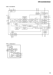
STR-DA2400ES/DG920 IC3800 ADV7392BCPZ HSYNC VSYNC SFL/MISO GND_IO P3 P2 P1 DGND VDD P0 40 39 38 37 36 35 34 33 32 VDD_IO 1 P4 2 ... 6 DGND 7 P8 8 P9 9 P10 10 VIDEO TIMING GENERATOR MULTIPLEXER 4:2:2 TO 4:4:4 INPUT DEINTERLEAVE RGB/YCrCb TO YUV MATRIX ASYNC BYPASS YCrCb ADD SYNC ADD BURST HDTV TEST PATTERN GENERATOR VBI DATA SERVICE INSERTION PROGRAMMABLE LUMINANCE FILTER PROGRAMMABLE CHROMINANCE FILTER PROGRAMMABLE ED/HD FILTERS SHARPNESS AND ADAPTIVE FILTER CONTROL YUV TO YCrCb/RGB...
STR-DA2400ES/DG920 IC3800 ADV7392BCPZ HSYNC VSYNC SFL/MISO GND_IO P3 P2 P1 DGND VDD P0 40 39 38 37 36 35 34 33 32 VDD_IO 1 P4 2 ... 6 DGND 7 P8 8 P9 9 P10 10 VIDEO TIMING GENERATOR MULTIPLEXER 4:2:2 TO 4:4:4 INPUT DEINTERLEAVE RGB/YCrCb TO YUV MATRIX ASYNC BYPASS YCrCb ADD SYNC ADD BURST HDTV TEST PATTERN GENERATOR VBI DATA SERVICE INSERTION PROGRAMMABLE LUMINANCE FILTER PROGRAMMABLE CHROMINANCE FILTER PROGRAMMABLE ED/HD FILTERS SHARPNESS AND ADAPTIVE FILTER CONTROL YUV TO YCrCb/RGB...
Service Manual
Page 99
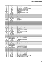
.../O N5 DVDD - K12 CVDD - M14 UHPI_HD[2] I/O M15, M16 EM_A[6], EM_A[5] O N1 EMU[1]# I/O N2, N3 UHPI_HD[25], UHPI_HD[26] I/O N4 EM_D[22] I K5 CVDD - STR-DA2400ES/DG920 Pin No. M5 VSS - N13, N14 UHPI_HD[5], UHPI_HD[6] I/O N15, N16 EM_A[8], EM_A[7] O P1 TCK I P2 UHPI_HD[24] I/O P3 to P7 EM_D[21] to N11... Two-way data bus with the SD-RAM Power supply terminal (+3.3V) (for IO) Not used Address signal output to the SD-RAM Test clock signal input terminal (for JTAG) Not used Two-way data bus with the SD-RAM Power supply terminal (+3.3V) (for IO) Two...
.../O N5 DVDD - K12 CVDD - M14 UHPI_HD[2] I/O M15, M16 EM_A[6], EM_A[5] O N1 EMU[1]# I/O N2, N3 UHPI_HD[25], UHPI_HD[26] I/O N4 EM_D[22] I K5 CVDD - STR-DA2400ES/DG920 Pin No. M5 VSS - N13, N14 UHPI_HD[5], UHPI_HD[6] I/O N15, N16 EM_A[8], EM_A[7] O P1 TCK I P2 UHPI_HD[24] I/O P3 to P7 EM_D[21] to N11... Two-way data bus with the SD-RAM Power supply terminal (+3.3V) (for IO) Not used Address signal output to the SD-RAM Test clock signal input terminal (for JTAG) Not used Two-way data bus with the SD-RAM Power supply terminal (+3.3V) (for IO) Two...
Service Manual
Page 101
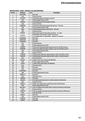
...I2SSCLK O I2S bit clock signal output to the system controller 4 VDD - STR-DA2400ES/DG920 MICON BOARD IC8003 F2602E-01-TR (XM RECEIVER) Pin No. Power supply terminal (+3.3V) 5 SCRXIN I XM receiver differential signal (negative) input from the system controller 6 VSS - Ground ... converter (for XM section) 44 VSS - Ground terminal 45 SAIICLK - Power supply terminal (+3.3V) 47 SAIIDATA - Ground terminal 30 TEST - Ground terminal 32 HSDPDATA - Not used 48 SAIIEN - Power supply terminal (+3.3V) 34 HSDPCLK - Power supply terminal (+3.3V) 41...
...I2SSCLK O I2S bit clock signal output to the system controller 4 VDD - STR-DA2400ES/DG920 MICON BOARD IC8003 F2602E-01-TR (XM RECEIVER) Pin No. Power supply terminal (+3.3V) 5 SCRXIN I XM receiver differential signal (negative) input from the system controller 6 VSS - Ground ... converter (for XM section) 44 VSS - Ground terminal 45 SAIICLK - Power supply terminal (+3.3V) 47 SAIIDATA - Ground terminal 30 TEST - Ground terminal 32 HSDPDATA - Not used 48 SAIIEN - Power supply terminal (+3.3V) 34 HSDPCLK - Power supply terminal (+3.3V) 41...


