Operating Instructions
Page 2
... interference that to Part 15 of Conformity Trade Name: SONY Model: SDM-HS75 SDM-HS95 Responsible Party: Sony Electronics Inc. Do not open the cabinet. If shipped to qualified personnel only. Owner's Record The model and serial numbers are located at the rear of the FCC rules. Model No. Refer servicing to USA/Canada, install only a UL LISTED/CSA LABELLED power supply cord meeting the following measures...
... interference that to Part 15 of Conformity Trade Name: SONY Model: SDM-HS75 SDM-HS95 Responsible Party: Sony Electronics Inc. Do not open the cabinet. If shipped to qualified personnel only. Owner's Record The model and serial numbers are located at the rear of the FCC rules. Model No. Refer servicing to USA/Canada, install only a UL LISTED/CSA LABELLED power supply cord meeting the following measures...
Operating Instructions
Page 3
Precautions 4 Identifying parts and controls 5 Setup 7 Step 1: Open the stand 7 Step 2: Connect the display to your computer 7 Step 3: Connect the power cord 8 Step 4: Secure the cords and replace the back cover 8 Step 5: Turn on -screen menu language (LANGUAGE 15 Additional settings 15 Technical Features 16 Power saving function 16 Reducing the power consumption ( mode 16 Automatic picture quality adjustment function 16 Troubleshooting 17 On-screen messages 17 Trouble symptoms and remedies 18 Specifications 20 http://www.sony.net/ 3 Table of Contents...
Precautions 4 Identifying parts and controls 5 Setup 7 Step 1: Open the stand 7 Step 2: Connect the display to your computer 7 Step 3: Connect the power cord 8 Step 4: Secure the cords and replace the back cover 8 Step 5: Turn on -screen menu language (LANGUAGE 15 Additional settings 15 Technical Features 16 Power saving function 16 Reducing the power consumption ( mode 16 Automatic picture quality adjustment function 16 Troubleshooting 17 On-screen messages 17 Trouble symptoms and remedies 18 Specifications 20 http://www.sony.net/ 3 Table of Contents...
Operating Instructions
Page 4
... this monitor must be installed near an open window or an outdoor exit. If a part of light (red, blue, or green) may appear constantly on the screen. The screen returns to lose uniformity or cause LCD panel malfunctions. • If the monitor is displayed for repair or shipment, use a different power cord, be sure that material deterioration or LCD screen coating degradation may appear on the LCD screen, and irregular colored stripes or brightness may...
... this monitor must be installed near an open window or an outdoor exit. If a part of light (red, blue, or green) may appear constantly on the screen. The screen returns to lose uniformity or cause LCD panel malfunctions. • If the monitor is displayed for repair or shipment, use a different power cord, be sure that material deterioration or LCD screen coating degradation may appear on the LCD screen, and irregular colored stripes or brightness may...

Operating Instructions
Page 5
... monitor is in green when the display is turned on the lower right part of the front of the screen. GB 6 Security Lock Hole The security lock hole should be applied with the Kensington Micro Saver Security System. The 1 (power) switch and the control buttons are on , and lights up in power saving mode. Front of the display 1 1 (Power) switch and indicator (pages 9, 16) To turn the display on or off . 2 MENU button...
... monitor is in green when the display is turned on the lower right part of the front of the screen. GB 6 Security Lock Hole The security lock hole should be applied with the Kensington Micro Saver Security System. The 1 (power) switch and the control buttons are on , and lights up in power saving mode. Front of the display 1 1 (Power) switch and indicator (pages 9, 16) To turn the display on or off . 2 MENU button...

Operating Instructions
Page 6
Rear of the display 7 7 Back cover (page 8) Remove this cover when you connect/disconnect cables or cords. 8 AC IN connector (page 8) Connect the power cord (supplied). 9 HD15 input connector (analog RGB) (page 7) This connector inputs analog RGB video signals (0.7 Vp-p, positive) and SYNC signals. Remove the back cover. 8 9 6
Rear of the display 7 7 Back cover (page 8) Remove this cover when you connect/disconnect cables or cords. 8 AC IN connector (page 8) Connect the power cord (supplied). 9 HD15 input connector (analog RGB) (page 7) This connector inputs analog RGB video signals (0.7 Vp-p, positive) and SYNC signals. Remove the back cover. 8 9 6
Operating Instructions
Page 7
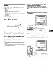
...; LCD display • Power cord • HD15-HD15 video signal cable (analog RGB) • Cord strap • CD-ROM (utility software for Windows/Macintosh, Operating Instructions, etc.) • Warranty card • Quick Setup Guide Step 1: Open the stand Connect a computer equipped with the stand as this monitor to a Macintosh computer, use the Macintosh adapter (not supplied) if necessary. to the computer's HD15 output connector (analog RGB) IBM PC/AT or compatible computer HD15-HD15 video signal cable (analog RGB) (supplied) GB x Connecting to a Macintosh computer When connecting...
...; LCD display • Power cord • HD15-HD15 video signal cable (analog RGB) • Cord strap • CD-ROM (utility software for Windows/Macintosh, Operating Instructions, etc.) • Warranty card • Quick Setup Guide Step 1: Open the stand Connect a computer equipped with the stand as this monitor to a Macintosh computer, use the Macintosh adapter (not supplied) if necessary. to the computer's HD15 output connector (analog RGB) IBM PC/AT or compatible computer HD15-HD15 video signal cable (analog RGB) (supplied) GB x Connecting to a Macintosh computer When connecting...
Operating Instructions
Page 9
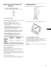
... the screen: Check that the video signal cable is automatically selected so that you turn on your screen • Check that the power cord and the video signal cable are unobtrusive on the monitor and computer 1 Press the 1 (power) switch upward. No need to set it is designed so that light is in green. The Plug & Play monitor is properly connected. • If OUT OF RANGE appears on the screen. You do not need for specific drivers The monitor...
... the screen: Check that the video signal cable is automatically selected so that you turn on your screen • Check that the power cord and the video signal cable are unobtrusive on the monitor and computer 1 Press the 1 (power) switch upward. No need to set it is designed so that light is in green. The Plug & Play monitor is properly connected. • If OUT OF RANGE appears on the screen. You do not need for specific drivers The monitor...

Operating Instructions
Page 10
... the best result. Each time you select LOW, the power consumption is set to sRGB, you select BACKLIGHT using the m/M and OK buttons. 1 BACKLIGHT (page 11) Select the BACKLIGHT menu to adjust the brightness of the backlight. 2 CONTRAST 6 (page 12) Select the CONTRAST menu to adjust the picture contrast. 3 BRIGHTNESS 8 (page 12) Select the BRIGHTNESS menu to adjust the picture brightness (black level). 4 SCREEN (page 12) Select the SCREEN menu to adjust the picture's sharpness (phase/pitch) or its centering (horizontal/vertical position). 5 COLOR...
... the best result. Each time you select LOW, the power consumption is set to sRGB, you select BACKLIGHT using the m/M and OK buttons. 1 BACKLIGHT (page 11) Select the BACKLIGHT menu to adjust the brightness of the backlight. 2 CONTRAST 6 (page 12) Select the CONTRAST menu to adjust the picture contrast. 3 BRIGHTNESS 8 (page 12) Select the BRIGHTNESS menu to adjust the picture brightness (black level). 4 SCREEN (page 12) Select the SCREEN menu to adjust the picture's sharpness (phase/pitch) or its centering (horizontal/vertical position). 5 COLOR...

Operating Instructions
Page 11
... m/M buttons to normal viewing. Press the MENU button once to return to make the screen easier to HIGH, 1 Press the MENU button. MENU x Resetting the adjustments You can reset the adjustments using the RESET menu. OK , 3 Adjust the menu. The BACKLIGHT menu appears on the screen. 3 Press the m/M buttons to adjust. MENU 2 Select the menu you press the OK button, the setting is too bright, adjust the backlight and make the adjustment, then press the OK button. OK , 4 Close the menu. If no buttons are...
... m/M buttons to normal viewing. Press the MENU button once to return to make the screen easier to HIGH, 1 Press the MENU button. MENU x Resetting the adjustments You can reset the adjustments using the RESET menu. OK , 3 Adjust the menu. The BACKLIGHT menu appears on the screen. 3 Press the m/M buttons to adjust. MENU 2 Select the menu you press the OK button, the setting is too bright, adjust the backlight and make the adjustment, then press the OK button. OK , 4 Close the menu. If no buttons are...
Operating Instructions
Page 12
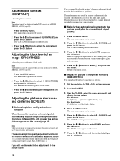
mode is set to select 6 (CONTRAST) and press the OK button. If the automatic picture quality adjustment function of the screen's phase, pitch and horizontal/vertical position for the current input signal (AUTO) 1 Press the MENU button. These adjustments are at a minimum. 12 The main menu appears on the screen. 3 Press the m/M buttons to select OK button. Return to select (SCREEN) and press the OK button. Adjusting the black level of the picture quality for the...
mode is set to select 6 (CONTRAST) and press the OK button. If the automatic picture quality adjustment function of the screen's phase, pitch and horizontal/vertical position for the current input signal (AUTO) 1 Press the MENU button. These adjustments are at a minimum. 12 The main menu appears on the screen. 3 Press the m/M buttons to select OK button. Return to select (SCREEN) and press the OK button. Adjusting the black level of the picture quality for the...
Operating Instructions
Page 13
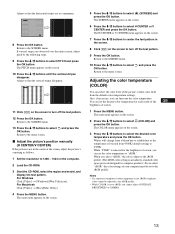
... picture's white color field from the default color temperature settings. If vertical stripes are at a minimum. 8 Press the OK button. Return to select OK button. and press the x Adjust the picture's position manually (H CENTER/V CENTER) If the picture is not in the screen. 8 Click [END] on the computer. 2 Load the CD-ROM. 3 Start the CD-ROM, select the region and model, and display the test pattern. While "USER" is set...
... picture's white color field from the default color temperature settings. If vertical stripes are at a minimum. 8 Press the OK button. Return to select OK button. and press the x Adjust the picture's position manually (H CENTER/V CENTER) If the picture is not in the screen. 8 Click [END] on the computer. 2 Load the CD-ROM. 3 Start the CD-ROM, select the region and model, and display the test pattern. While "USER" is set...

Operating Instructions
Page 14
The USER ADJUSTMENT menu appears on the screen. 3 Press the m/M buttons to select R (Red) or B (Blue) and press the OK button. The main menu appears on the screen. 2 Press the m/M buttons to adjust the color temperature and press the OK button. The GAMMA menu appears on the screen. 2 Press the m/M buttons to select the desired mode and press the OK button. Changing the menu's position (MENU POSITION) You can associate the picture's color shade on the screen. 2 Press...
The USER ADJUSTMENT menu appears on the screen. 3 Press the m/M buttons to select R (Red) or B (Blue) and press the OK button. The main menu appears on the screen. 2 Press the m/M buttons to adjust the color temperature and press the OK button. The GAMMA menu appears on the screen. 2 Press the m/M buttons to select the desired mode and press the OK button. Changing the menu's position (MENU POSITION) You can associate the picture's color shade on the screen. 2 Press...

Operating Instructions
Page 15
... the on-screen menu language (LANGUAGE) You can change the language used on menus or messages displayed on the screen. 2 Press the m/M buttons to select the desired mode and press the OK button. • OK: To reset all of the adjustment data to the default settings. x Locking the menus and controls You can adjust the following instructions. GB 15 The RESET menu appears on this monitor. 1 Press the MENU button. If you set the (MENU LOCK) item to...
... the on-screen menu language (LANGUAGE) You can change the language used on menus or messages displayed on the screen. 2 Press the m/M buttons to select the desired mode and press the OK button. • OK: To reset all of the adjustment data to the default settings. x Locking the menus and controls You can adjust the following instructions. GB 15 The RESET menu appears on this monitor. 1 Press the MENU button. If you set the (MENU LOCK) item to...
Operating Instructions
Page 16
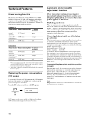
... following monitor frequency ranges): Horizontal frequency: 28-80 kHz Vertical frequency: 48-75 Hz Consequently, the first time the monitor receives input signals that next time, the monitor will automatically reduce power consumption as user modes and automatically recalled whenever the monitor receives the same input signals. If you can set these adjustments manually (page 12). In this case, you adjust the phase, pitch, and picture position manually For some input signals, the automatic picture quality adjustment function...
... following monitor frequency ranges): Horizontal frequency: 28-80 kHz Vertical frequency: 48-75 Hz Consequently, the first time the monitor receives input signals that next time, the monitor will automatically reduce power consumption as user modes and automatically recalled whenever the monitor receives the same input signals. If you can set these adjustments manually (page 12). In this case, you adjust the phase, pitch, and picture position manually For some input signals, the automatic picture quality adjustment function...
Operating Instructions
Page 17
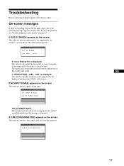
... RANGE x x x . If CABLE DISCONNECTED appears on the screen. To solve the problem, see "Trouble symptoms and remedies" on the screen This indicates that no signal is something wrong with the input signal, one of the current input signal. If "RESOLUTION > 1280 × 1024" is displayed. If NO INPUT SIGNAL appears on page 18. I NFORMA T I ON CAB L E D I GNA L GO TO POWER SAVE GO TO POWER SAVE The monitor will enter the power saving mode...
... RANGE x x x . If CABLE DISCONNECTED appears on the screen. To solve the problem, see "Trouble symptoms and remedies" on the screen This indicates that no signal is something wrong with the input signal, one of the current input signal. If "RESOLUTION > 1280 × 1024" is displayed. If NO INPUT SIGNAL appears on page 18. I NFORMA T I ON CAB L E D I GNA L GO TO POWER SAVE GO TO POWER SAVE The monitor will enter the power saving mode...
Operating Instructions
Page 18
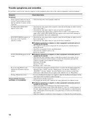
... graphics board manual for the monitor to sync correctly. • Adjust the computer's refresh rate (vertical frequency) to the connected equipment's instruction manual. Select "SONY" from the "Manufacturers" list and select "SDM-HS75" or "SDM-HS95" from the "Models" list in . • A non-supplied video signal cable is on the screen before entering the power saving mode. If CABLE DISCONNECTED appears on the screen, • Check that the video signal cable is properly connected and all plugs are firmly seated in the power saving mode...
... graphics board manual for the monitor to sync correctly. • Adjust the computer's refresh rate (vertical frequency) to the connected equipment's instruction manual. Select "SONY" from the "Manufacturers" list and select "SDM-HS75" or "SDM-HS95" from the "Models" list in . • A non-supplied video signal cable is on the screen before entering the power saving mode. If CABLE DISCONNECTED appears on the screen, • Check that the video signal cable is properly connected and all plugs are firmly seated in the power saving mode...
Operating Instructions
Page 19
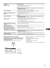
... menu lock is receiving a video signal, press and hold the MENU button for the display to become bright after a while Resolution displayed on the menu screen is fuzzy Check these items • Adjust the brightness and contrast (page 12). • Adjust the pitch and phase (page 12). NO : 1234567 MANUFACTURED : 2004-52 Model name Serial number Week and year of your computer and graphics board Example INFORMATION MODEL : SDM-HS75 SER . Picture is ghosting Picture...
... menu lock is receiving a video signal, press and hold the MENU button for the display to become bright after a while Resolution displayed on the menu screen is fuzzy Check these items • Adjust the brightness and contrast (page 12). • Adjust the pitch and phase (page 12). NO : 1234567 MANUFACTURED : 2004-52 Model name Serial number Week and year of your computer and graphics board Example INFORMATION MODEL : SDM-HS75 SER . Picture is ghosting Picture...
Operating Instructions
Page 20
Specifications SDM-HS75 LCD panel Panel type: a-Si TFT Active Matrix Picture size: 17.0 inch Input signal format RGB operating frequency* Horizontal: 28-80 kHz Vertical: 48-75 Hz Resolution Horizontal: Max.1280 dots Vertical: Max.1024 lines Input signal levels Analog RGB video signal 0.7 Vp-p, 75 Ω, positive SYNC signal TTL level, 2.2 kΩ, positive or negative (Separate horizontal and vertical) Power requirements 100-240 V, 50-60 Hz, Max. 1.0 A Power consumption Max. 45 W Operating temperature 5-35 °C Dimensions (width/height/depth) Display (upright...
Specifications SDM-HS75 LCD panel Panel type: a-Si TFT Active Matrix Picture size: 17.0 inch Input signal format RGB operating frequency* Horizontal: 28-80 kHz Vertical: 48-75 Hz Resolution Horizontal: Max.1280 dots Vertical: Max.1024 lines Input signal levels Analog RGB video signal 0.7 Vp-p, 75 Ω, positive SYNC signal TTL level, 2.2 kΩ, positive or negative (Separate horizontal and vertical) Power requirements 100-240 V, 50-60 Hz, Max. 1.0 A Power consumption Max. 45 W Operating temperature 5-35 °C Dimensions (width/height/depth) Display (upright...
Marketing Specifications (Black model)
Page 1
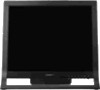
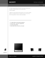
It's Sony's best value display. s 19" display (1280 x 1024) (measured diagonally) s 250 cd/m2, 500:1, 16ms video response time s PC Inputs: Analog (HD15) s Black metallic frame with wall-mountability. Images are crisp and fast-moving whether you 're up and running quickly. It's simple to set up so you 're working, playing games or browsing the web. SDM-HS95B IT Display The HS95 display features a slender rising design that gives you the option of small footprint or zero footprint with a silver control panel
It's Sony's best value display. s 19" display (1280 x 1024) (measured diagonally) s 250 cd/m2, 500:1, 16ms video response time s PC Inputs: Analog (HD15) s Black metallic frame with wall-mountability. Images are crisp and fast-moving whether you 're up and running quickly. It's simple to set up so you 're working, playing games or browsing the web. SDM-HS95B IT Display The HS95 display features a slender rising design that gives you the option of small footprint or zero footprint with a silver control panel
Marketing Specifications (Black model)
Page 2
...-free. Sony's automatic image adjustment feature optimizes your display's performance instantly. Non-metric weights and measures are trademarks of their respective owners Features and specifications are subject to change without notice. Specifications PART NUMBER IMAGE SIZE DISPLAY NATIVE RESOLUTION CONTRAST RATIO ERGOBRIGHT™ TECHNOLOGY HORIZONTAL SCAN (KHZ) VERTICAL REFRESH (HZ) VIEWING ANGLE TILT RANGE VIDEO INPUT CONNECTOR POWER MANAGEMENT SHIPPING MEASUREMENTS LIMITED WARRANTY SCREEN COATING ERGOSTAND™ SYSTEM VESA WALL/ARM MOUNT KENSINGTON LOCK INTERNAL POWER SUPPLY POWER...
...-free. Sony's automatic image adjustment feature optimizes your display's performance instantly. Non-metric weights and measures are trademarks of their respective owners Features and specifications are subject to change without notice. Specifications PART NUMBER IMAGE SIZE DISPLAY NATIVE RESOLUTION CONTRAST RATIO ERGOBRIGHT™ TECHNOLOGY HORIZONTAL SCAN (KHZ) VERTICAL REFRESH (HZ) VIEWING ANGLE TILT RANGE VIDEO INPUT CONNECTOR POWER MANAGEMENT SHIPPING MEASUREMENTS LIMITED WARRANTY SCREEN COATING ERGOSTAND™ SYSTEM VESA WALL/ARM MOUNT KENSINGTON LOCK INTERNAL POWER SUPPLY POWER...


