User's Guide
Page 11
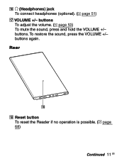
(Headphones) jack To connect headphones (optional). ( page 51) VOLUME +/- Rear Reset button To reset the Reader if no operation is possible. ( page 68) Continued 11 US To restore the sound, press the VOLUME +/- buttons. buttons To adjust the volume. ( page 53) To mute the sound, press and hold the VOLUME +/- buttons again.
(Headphones) jack To connect headphones (optional). ( page 51) VOLUME +/- Rear Reset button To reset the Reader if no operation is possible. ( page 68) Continued 11 US To restore the sound, press the VOLUME +/- buttons. buttons To adjust the volume. ( page 53) To mute the sound, press and hold the VOLUME +/- buttons again.
User's Guide
Page 68
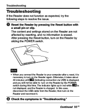
... via USB) is displayed, and you connect the Reader to your computer after a reset, it . Check the symptoms in red while is not displayed, and the Reader is erased. Continued 68 US After pressing the Reset button, turn on the Reader are not affected by pressing the Reset button with a small pin or clip. The indicator lights...
... via USB) is displayed, and you connect the Reader to your computer after a reset, it . Check the symptoms in red while is not displayed, and the Reader is erased. Continued 68 US After pressing the Reset button, turn on the Reader are not affected by pressing the Reset button with a small pin or clip. The indicator lights...
User's Guide
Page 95
...Index menu 43, 45 Indicator 9 Information 42 L Link 39 P Picture 55 POWER switch 9, 15 R Reading books 35 while playing an audio file.....53 Reset 68 Reset button 11, 68 RTF file 25, 38 M Manual 2 Media slot 9, 19 "Memory Stick Duo" slot.........9 SD Memory Card slot 9 Memory Card 19 ..."Memory Stick Duo 19, 86 MENU button 9, 13 N NEXT button 38 Number button...........9, 36, 51, 55 Number tab 36, 51, 55 O Option menu 13, 37 S SD ...
...Index menu 43, 45 Indicator 9 Information 42 L Link 39 P Picture 55 POWER switch 9, 15 R Reading books 35 while playing an audio file.....53 Reset 68 Reset button 11, 68 RTF file 25, 38 M Manual 2 Media slot 9, 19 "Memory Stick Duo" slot.........9 SD Memory Card slot 9 Memory Card 19 ..."Memory Stick Duo 19, 86 MENU button 9, 13 N NEXT button 38 Number button...........9, 36, 51, 55 Number tab 36, 51, 55 O Option menu 13, 37 S SD ...

Service Manual
Page 5
...a menu. (page) / (>/)/ previous ( Enter button buttons*1 To select an item or scroll around the screen, press (left), (up), (down), or (right). *1 In this manual, the operation of the Enter buttons are explained as follows. (Example) Press to select "Away"... on the Book list, then press Enter. MENU button To return to Parts and Controls Holes for soft cover attachment The soft cover is extracted from instruction manual. SECTION 2 GENERAL PRS-505 This...
...a menu. (page) / (>/)/ previous ( Enter button buttons*1 To select an item or scroll around the screen, press (left), (up), (down), or (right). *1 In this manual, the operation of the Enter buttons are explained as follows. (Example) Press to select "Away"... on the Book list, then press Enter. MENU button To return to Parts and Controls Holes for soft cover attachment The soft cover is extracted from instruction manual. SECTION 2 GENERAL PRS-505 This...
Service Manual
Page 11
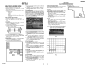
... the [ENTER] button or [5] button. 2. VCOM adjustment is press the [ENTER] button or [3] button, it is required when replacing a board or panel. MAIN Board (Component Side) - With the "Pictures" tab in the factory. Update Waveform In this mode. 1. PRS-505 11 SECTION 5 ELECTRICAL ADJUSTMENT PRS-505 VCOM VOLTAGE ADJUSTMENT ...Sony Reader/software" on OK. After the end of test, a display of Test Panel on an oscilloscope (refer to Fig.2), and use RV1801 to adjust the voltage that it is changed so that is generated when the screen is back to check that the Reset...
... the [ENTER] button or [5] button. 2. VCOM adjustment is press the [ENTER] button or [3] button, it is required when replacing a board or panel. MAIN Board (Component Side) - With the "Pictures" tab in the factory. Update Waveform In this mode. 1. PRS-505 11 SECTION 5 ELECTRICAL ADJUSTMENT PRS-505 VCOM VOLTAGE ADJUSTMENT ...Sony Reader/software" on OK. After the end of test, a display of Test Panel on an oscilloscope (refer to Fig.2), and use RV1801 to adjust the voltage that it is changed so that is generated when the screen is back to check that the Reset...

