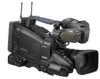
Specification Sheet (CBK-WA100/CBK-WA101 Wireless Adapters)
Page 1
...models are an ideal choice for ENG professionals when the speed of the adapter such as high resolution file transmission, basic remote camera control, wireless adapter status indication on the viewfinder and more. Some models are required. the wireless adapter can be used, ...inches (84 x 95 x 55 mm) without Wireless Data Transfer Shooting Media Transport Lead Time with DC power output IFU-WLM3 USB Wireless LAN Module Sony Product Wireless LAN USB Device IFU-WLM3 is recommended. Smartphone or Tablet To view a streaming content, a terminal (a Smartphone or a Tablet) and ...
Specification Sheet (CBK-WA100/CBK-WA101 Wireless Adapters)
Page 2
...in the field The wireless adapter can be previewed on -premise server or to change setting, select device, control camera*10, and trigger file transfer. Select file and upload Recorded clips can enjoy all of the features of Wi-Fi ... function does not allow simultaneous use of the wireless adapter. Camera Control Camera Control Camera Control Sony Electronics Inc. 1 Sony Drive Park Ridge, NJ 07656 sony.com/xdcam V-2580-A (MK11075V1) Video Streaming Camera Control (Simulated Images) ©2013 Sony Electronics Inc. Features, design, and specifications are unavailable for ...
Product Manual (PMW320 Operating Instruction)
Page 9
Operating Clips with a Computer 143 Connecting an External Device (i.LINK Connection 145 Recording the Camera Picture on an External Device 145 Nonlinear Editing 146 Recording External Input Signals 146 Chapter 9 : Maintenance Testing the Camcorder 148 Maintenance ...Battery Terminal 148 Operation Warnings 149 Appendix Important Notes on Operation 156 Exchanging the Battery of the Internal Clock 158 Specifications 158 General 158 Camera Block 159 Audio Block 159 Display 159 Media Block 160 Inputs/Outputs 160 Lens Block (PMW-320K only 160 Supplied Accessories 161 Recommended...
Product Manual (PMW320 Operating Instruction)
Page 15
... clamp Clamp a lens cable. Note The auto iris function is not used for connecting the lens. Chapter 1 Overview c Viewfinder front-to the camera. On the inner side of the viewfinder (see page 35). r Lens locking lever After inserting the lens in the front-toback direction, loosen ..., round) Connect the cable of the supplied viewfinder. For connecting the DXF-51 or DXF-C50W, optional parts are also disabled. Consult a Sony service representative for information about connecting the DXF-51 or DXF-C50W. h Lens mount securing rubber After locking the lens in position. j Fitting...
Product Manual (PMW320 Operating Instruction)
Page 18
... this switch functions as the MENU CANCEL/PRST/ESCAPE switch. (To use . Off is assigned to this switch when the camcorder is shipped from the camera module, between the following way. BARS: Output the color bar signal. PRST: Adjust the color temperature to the preset value (the factory default setting: 3200K...
Product Manual (PMW320 Operating Instruction)
Page 23
... it as an external storage device for a computer. b USB connector Used to put this button to select the card you can monitor picture being shot (camera picture) or playback picture. This makes the media come out of the slot partially (see page 67). System frequency 1080/59.94i 1080/29.97P...
Product Manual (PMW320 Operating Instruction)
Page 24
.... These indicators also flash to the timecode of OPERATION >Input/Output >Output&i.LINK in speaker. k VIDEO OUT connector (BNC type) Outputs video signals for the camera module supports horizontal sync signals only.) Use MAINTENANCE >GENLOCK in the setup menu to adjust the genlock H-phase (phase of the viewfinder and the REC...
Product Manual (PMW320 Operating Instruction)
Page 29
...: The lens extender and the optional digital extender function of the lens extender. d Green tally Lights when the camcorder is the following states. • MAINTENANCE >Camera Config >HD-SDI Remote I/F is enabled e Media status Displays the name of the screen. f Recording mode/operation status Indicates the current recording mode/operation status...
Product Manual (PMW320 Operating Instruction)
Page 31
...* (Manual Focus mode when the MF Assist function is on) • Full MF (Full Manual Focus mode) c External device control "REC2" is displayed when MAINTENANCE >Camera Config >HD-SDI Remote I/F is set to [Chara] in time units of minutes. When ELECTRICAL CC is assigned to an assignable switch, the electrical filter...
Product Manual (PMW320 Operating Instruction)
Page 42
...aberration correction lens The aberration correction function is an aberration correction lens. Arrange so that it . 6 Set the zoom ring to the camera than normally because of data loading at start-up. Make this will cause an adjustment error. • Place the subject (the ... focus on the lens locking lever as illustrated above. If the adjustment completes correctly The message on the viewfinder screen. Contact a Sony service representative for 3 seconds. If the flange focal length adjustment does not complete correctly Check the subject and lighting conditions, and repeat...
Product Manual (PMW320 Operating Instruction)
Page 46
... position even after the camcorder is removed. Slide the camcorder forward along the groove in the direction of the arrow. 46 Tripod Mounting Tripod adaptor Camera mount 2 Mount the camcorder on the tripod adaptor. If this happens, press the red button and move the lever as shown above until it clicks...
Product Manual (PMW320 Operating Instruction)
Page 64
... information related to audio input and output Settings and status information related to recording and playback Names of functions assigned to the ON/SEL side. CAMERA status screen This screen displays settings and status information related to assignable switches White Bal: White balance status Gain: GAIN switch status Zoom Speed: Zoom...
Product Manual (PMW320 Operating Instruction)
Page 70
...other card slot. Marker display: On (see page 103) Iris: Auto (see page 56) Zoom: Auto (see page 57) Camera output: Select the picture currently being shot (camera picture), and turn the DCC function on (see page 14) to verify that it is in progress, you are using this ...explains the basic shooting and recording procedures. Chapter 4 Shooting 3 Copy the required clips back to use this camcorder. Before starting to shoot, inspect the camera system to ON. 4 Make the following to the second card when the first card becomes full. 3 Set the camcorder's POWER switch (see page ...
Product Manual (PMW320 Operating Instruction)
Page 71
... to 46 characters in length). (A user-specified prefix cannot be changed after stopping recording. • The maximum number of clips that can also use MAINTENANCE >Camera Config >Rec Review in the setup menu (see page 132). Playing Recorded Clips When the camcorder is lit). Notes • Never remove the battery pack...
Product Manual (PMW320 Operating Instruction)
Page 79
... of the following cases. • When the recording format is SP 1440/23.98P • When the video formats of the recorded picture and the camera picture differ • When you are disabled at the freeze mix times. • Menu operations • During Focus Mag display • Marker display ... cancel the freeze mix display Do one of a clip with the Freeze Mix Function The freeze mix function allows you want to use as the camera picture. 2 Display the picture that you to which the Freeze Mix function has been assigned. Note The following functions are shooting in the following ...
Product Manual (PMW320 Operating Instruction)
Page 82
... continues through all clips thumbnail screen, or when you have been split into playback mode, pause, use the PREV button to return to display the camera picture. For example, while an HD mode thumbnail screen is paused. To play at the top of the clip. To return to select. • ...transition from one of the following to move the yellow cursor to the clip that you select a clip in the viewfinder. During this case, the camera picture appears in the normal thumbnail screen, the OK clip thumbnail screen, or the all clips after the clip name (delimited by pressing the SLOT...
Product Manual (PMW320 Operating Instruction)
Page 85
...-item, a selection list or a clip properties screen appears (see page 86). The THUMBNAIL menu appears. Press the THUMBNAIL button: The camcorder enters E-E mode, and the camera picture appears. When the normal thumbnail screen is not possible to copy, delete, or divide clips, to change index pictures, or to add and delete...
Product Manual (PMW320 Operating Instruction)
Page 93
... item that you want to set Language Hours Meter Version FILE Menu (see page 116) MAINTENANCE White Shading Battery Audio WRR Setting Timecode Essence Mark Camera Config Preset White White Filter Auto Iris2 Flicker Reduce Genlock ND Comp Lens Trigger Mode Clock set . Basic Setup Menu Operations 93 Chapter 6 Menu and...
Product Manual (PMW320 Operating Instruction)
Page 95
... the initial value 1 Before a setting is reset to the initial value, push the MENU CANCEL/ PRST/ESCAPE switch up to the ESCAPE side. The normal camera picture reappears. Basic Setup Menu Operations 95 Chapter 6 Menu and Detailed Settings 1 Turn the MENU knob, or press the J or j button, to OFF or press...
Product Manual (PMW320 Operating Instruction)
Page 98
... related to I /O SDI Output HDMI Output SDI/HDMI Out Super Video Out Super Settings HD&HDV/SD&HDV/ SD&DV/480P (576P) PsF/Pull Down Camera/i.LINK Enable/Disable On/Off On/Off On/Off On/Off Description Selects the signals output from the video connectors and the i.LINK (HDV/DV... Output Source Select i.LINK I /O signals. When the video format is HQ 1920/ 23.98P or HQ 1440/23.98P, selects whether to use the video camera picture (Camera) or the signal input from the HDMI connector. Turns on or off the output of signals via the i.LINK (HDV/DV) connector.