Operating Instructions
Page 2
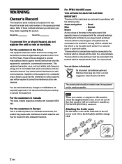
... case the user will not conform to comply with Canadian ICES003. Note When you connect a computer to Part 15 of the FCC Rules. To prevent fire or shock hazard, do this, this equipment. For PFM-510A1WE users THIS APPARATUS MUST BE EARTHED IMPORTANT The wires in this mains lead are coloured in... in the U.S.A. For the customers in the spaces provided below. If you call upon your authority to the terminal in this manual could void your Sony dealer regarding this monitor, attach the supplied ferrite cores.
... case the user will not conform to comply with Canadian ICES003. Note When you connect a computer to Part 15 of the FCC Rules. To prevent fire or shock hazard, do this, this equipment. For PFM-510A1WE users THIS APPARATUS MUST BE EARTHED IMPORTANT The wires in this mains lead are coloured in... in the U.S.A. For the customers in the spaces provided below. If you call upon your authority to the terminal in this manual could void your Sony dealer regarding this monitor, attach the supplied ferrite cores.
Operating Instructions
Page 3
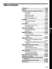
Table of Contents Precautions 4 (GB) Features 5 (GB) Location and Function of Parts and Controls ....... 6 (GB) Front / Sides 6 (GB) Control Panel 7 (GB) Right Connector Panel 8 (GB) Left Connector Panel 10 (GB) Remote Commander RM-921 10 (GB) Installation ...
Table of Contents Precautions 4 (GB) Features 5 (GB) Location and Function of Parts and Controls ....... 6 (GB) Front / Sides 6 (GB) Control Panel 7 (GB) Right Connector Panel 8 (GB) Left Connector Panel 10 (GB) Remote Commander RM-921 10 (GB) Installation ...
Operating Instructions
Page 4
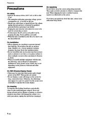
... the cabinet. As a safety precaution, unplug the unit before operating it any questions about this unit, contact your authorized Sony dealer. 4 (GB) On PDP (Plasma Display Panel) • There may appear on a part of the unit and other equipment. Never use the retractable feet. If you install multiple equipment with a mild detergent...
... the cabinet. As a safety precaution, unplug the unit before operating it any questions about this unit, contact your authorized Sony dealer. 4 (GB) On PDP (Plasma Display Panel) • There may appear on a part of the unit and other equipment. Never use the retractable feet. If you install multiple equipment with a mild detergent...
Operating Instructions
Page 6
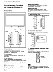
... page. 4 Left connector panel For details on the left connector panel, see "Left Connector Panel" on this cover. Location and Function of Parts and Controls Location and Function of Parts and Controls Front / Sides Front 5 Right connector panel For details on the right connector panel, see "Right Connector Panel" on page 8 (GB...
... page. 4 Left connector panel For details on the left connector panel, see "Left Connector Panel" on this cover. Location and Function of Parts and Controls Location and Function of Parts and Controls Front / Sides Front 5 Right connector panel For details on the right connector panel, see "Right Connector Panel" on page 8 (GB...

Operating Instructions
Page 7
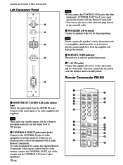
The 1 (standby) indicator lights up or flash that show they can be operated. Control Panel Location and Function of Parts and Controls VOL - Press again to go back to make the menu appear. qs MENU button Press to the standby mode. buttons Press the + button ...
The 1 (standby) indicator lights up or flash that show they can be operated. Control Panel Location and Function of Parts and Controls VOL - Press again to go back to make the menu appear. qs MENU button Press to the standby mode. buttons Press the + button ...

Operating Instructions
Page 8
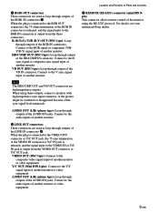
... VIDEO IN (BNC-type): Connect to the audio output of the video equipment. AUDIO IN (L/R) (phono type): Connect to the composite video signal output of Parts and Controls Right Connector Panel 1 2 3 RGB 1 IN OUT R R-Y G Y B B-Y HD/ COMP VD SYNC L AUDIO R RGB 2 RGB IN L AUDIO IN R VIDEO Y/C L AUDIO R IN OUT LINE REMOTE (RS...
... VIDEO IN (BNC-type): Connect to the audio output of the video equipment. AUDIO IN (L/R) (phono type): Connect to the composite video signal output of Parts and Controls Right Connector Panel 1 2 3 RGB 1 IN OUT R R-Y G Y B B-Y HD/ COMP VD SYNC L AUDIO R RGB 2 RGB IN L AUDIO IN R VIDEO Y/C L AUDIO R IN OUT LINE REMOTE (RS...
Operating Instructions
Page 9
...-through outputs of another monitor or video equipment. VD OUT (BNC-type): Loop-through output of another monitor or video equipment. Location and Function of Parts and Controls 6 REMOTE (RS-232C) connector (mini DIN 8pin) This connector allows remote control of the RGB IN connectors. R (R-Y)/G (Y)/B (B-Y) OUT (BNC-type): Loopthrough outputs of...-through outputs of another monitor or video equipment. Connect to the composite video signal input of the RGB1 IN connectors 1. For details, see your authorized Sony dealer. 9 (GB)
...-through outputs of another monitor or video equipment. VD OUT (BNC-type): Loop-through output of another monitor or video equipment. Location and Function of Parts and Controls 6 REMOTE (RS-232C) connector (mini DIN 8pin) This connector allows remote control of the RGB IN connectors. R (R-Y)/G (Y)/B (B-Y) OUT (BNC-type): Loopthrough outputs of...-through outputs of another monitor or video equipment. Connect to the composite video signal input of the RGB1 IN connectors 1. For details, see your authorized Sony dealer. 9 (GB)
Operating Instructions
Page 10
... (mini jacks) Connect to the CONTROL S jacks of an audio amplifier (not supplied). Once you can use the stereo cable with mini plug instead of Parts and Controls Left Connector Panel MONITOR OUT AUDIO R L VARIABLE CONTROL S IN OUT SPEAKERS (6-16 Ω) + + R- Note These jacks are variable outputs. Then you connect the...
... (mini jacks) Connect to the CONTROL S jacks of an audio amplifier (not supplied). Once you can use the stereo cable with mini plug instead of Parts and Controls Left Connector Panel MONITOR OUT AUDIO R L VARIABLE CONTROL S IN OUT SPEAKERS (6-16 Ω) + + R- Note These jacks are variable outputs. Then you connect the...
Operating Instructions
Page 11
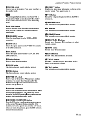
... press the index number of the monitor you can use this switch to turn monitors which are already on the screen. Location and Function of Parts and Controls qs DISPLAY button Displays the input signal information on the top of the POWER switch 1 not to affect another monitor which is already...
... press the index number of the monitor you can use this switch to turn monitors which are already on the screen. Location and Function of Parts and Controls qs DISPLAY button Displays the input signal information on the top of the POWER switch 1 not to affect another monitor which is already...
Operating Instructions
Page 12
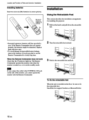
Location and Function of Parts and Controls / Installation Installing batteries Insert two size AA (R6) batteries in correct polarity. Be sure to install the negative
Location and Function of Parts and Controls / Installation Installing batteries Insert two size AA (R6) batteries in correct polarity. Be sure to install the negative
