
System Reference Manual
Page 12
xii VAIO Digital Studio™ System Reference Manual Chapter 3 - Removing, Installing, and Replacing Components 27 Removing the Side Cover 28 Replacing the Side Cover 29 Installing a PCI Add-In ... models 46 To set up the new hard drive with the startup disk (PCV-RX490TV model only 49 To identify the additional hard disk space for Giga Pocket use (PCV-RX490TV model only 49 Removing the Power Supply 50 Replacing the Power Supply 51 Chapter 4 - System Board 53 Connectors and Headers 54 Front Panel Header 54...
xii VAIO Digital Studio™ System Reference Manual Chapter 3 - Removing, Installing, and Replacing Components 27 Removing the Side Cover 28 Replacing the Side Cover 29 Installing a PCI Add-In ... models 46 To set up the new hard drive with the startup disk (PCV-RX490TV model only 49 To identify the additional hard disk space for Giga Pocket use (PCV-RX490TV model only 49 Removing the Power Supply 50 Replacing the Power Supply 51 Chapter 4 - System Board 53 Connectors and Headers 54 Front Panel Header 54...

System Reference Manual
Page 22
A 4-pin i.LINK header cannot supply power to a digital device that has a 4-pin i.LINK header. 8 VAIO Digital Studio™ System Reference Manual Connectors PCV-RX462DS/PCV-RX463DS/PCV-RX465DS/PCV-RX470DS/PCV-RX480DS USB3, USB4 i.LINK Connector i.LINK® (IEEE1394)* USB3, USB4 Description Connects to the device. Connects to USB devices. * To connect to the device if the device also has a 6-pin i.LINK header. A 6-pin i.LINK header can supply power from the computer to a 6-pin i.LINK device, use the i.LINK header on the back of the system.
A 4-pin i.LINK header cannot supply power to a digital device that has a 4-pin i.LINK header. 8 VAIO Digital Studio™ System Reference Manual Connectors PCV-RX462DS/PCV-RX463DS/PCV-RX465DS/PCV-RX470DS/PCV-RX480DS USB3, USB4 i.LINK Connector i.LINK® (IEEE1394)* USB3, USB4 Description Connects to the device. Connects to USB devices. * To connect to the device if the device also has a 6-pin i.LINK header. A 6-pin i.LINK header can supply power from the computer to a 6-pin i.LINK device, use the i.LINK header on the back of the system.
System Reference Manual
Page 31
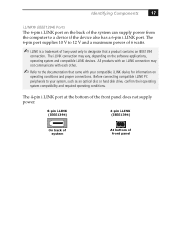
...operating conditions. Identifying Components 17 i.LINK® (IEEE1394) Ports The 6-pin i.LINK port on the back of the system can supply power from the computer to designate that came with each other. ✍ Refer to your compatible i.LINK device for information on the software applications, ...trademark of front panel The 4-pin i.LINK port at the bottom of the front panel does not supply power. 6-pin i.LINK (IEEE1394) 4-pin i.LINK (IEEE1394) On back of system At bottom of Sony used only to a device if the device also has a 6-pin i.LINK port. Before connecting compatible...
...operating conditions. Identifying Components 17 i.LINK® (IEEE1394) Ports The 6-pin i.LINK port on the back of the system can supply power from the computer to designate that came with each other. ✍ Refer to your compatible i.LINK device for information on the software applications, ...trademark of front panel The 4-pin i.LINK port at the bottom of the front panel does not supply power. 6-pin i.LINK (IEEE1394) 4-pin i.LINK (IEEE1394) On back of system At bottom of Sony used only to a device if the device also has a 6-pin i.LINK port. Before connecting compatible...
System Reference Manual
Page 42
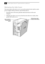
28 VAIO Digital Studio™ System Reference Manual Removing the Side Cover You must remove the side cover to release front panel Pull out top a few inches, then lift out Pull out tab to access the system board, add-in cards, power supply, battery, memory, and internal drives. 1 From the rear of the unit, pull the metal tab shown in the next diagram. 2 Pull the top of the cover away from the unit about two inches, then gently lift out the cover.
28 VAIO Digital Studio™ System Reference Manual Removing the Side Cover You must remove the side cover to release front panel Pull out top a few inches, then lift out Pull out tab to access the system board, add-in cards, power supply, battery, memory, and internal drives. 1 From the rear of the unit, pull the metal tab shown in the next diagram. 2 Pull the top of the cover away from the unit about two inches, then gently lift out the cover.
System Reference Manual
Page 47
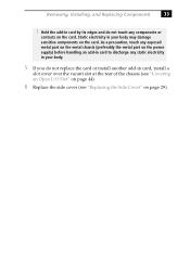
... touch any components or contacts on the card. As a precaution, touch any exposed metal part on the metal chassis (preferably the metal part on the power supply) before handling an add-in card to discharge any static electricity in your body may damage sensitive components on page 29). Removing, Installing, and Replacing...
... touch any components or contacts on the card. As a precaution, touch any exposed metal part on the metal chassis (preferably the metal part on the power supply) before handling an add-in card to discharge any static electricity in your body may damage sensitive components on page 29). Removing, Installing, and Replacing...

System Reference Manual
Page 51
...replace (see "Removing the Power Supply" on the handle at least 128 MB of the memory modules. Removing, Installing, and Replacing Components 37 Installing System Memory ! Your model may ship with at the edge of the chassis to the chassis. 7 Press down the computer, and unplug the power cord. 1 Choose the... models ship with more than 128 MB of either RIMM or CRIMM modules. 2 If necessary, remove the memory module you purchased it through the VAIO Direct Web site. ✍ Use only PC-800 Rambus RIMM memory modules. Before opening the system unit, save and close all open files, ...
...replace (see "Removing the Power Supply" on the handle at least 128 MB of the memory modules. Removing, Installing, and Replacing Components 37 Installing System Memory ! Your model may ship with at the edge of the chassis to the chassis. 7 Press down the computer, and unplug the power cord. 1 Choose the... models ship with more than 128 MB of either RIMM or CRIMM modules. 2 If necessary, remove the memory module you purchased it through the VAIO Direct Web site. ✍ Use only PC-800 Rambus RIMM memory modules. Before opening the system unit, save and close all open files, ...

System Reference Manual
Page 52
...preferably the metal part on the power supply) before handling an add-in card to side. ! The Giga Pocket card is a fragile hardware component, standard in PCI slot No. 2) unless directed by its edges and do not touch any components or contacts on the card. 38 VAIO Digital Studio™ System Reference Manual 8 ... Hold the add-in your body. ! Static electricity in card by a service technician. Do not remove the Giga Pocket card (located in the PCV-RX490TV model. 9 Align the module over the appropriate socket, noting the location of pin 1 on the module and pin 1 on the socket.
...preferably the metal part on the power supply) before handling an add-in card to side. ! The Giga Pocket card is a fragile hardware component, standard in PCI slot No. 2) unless directed by its edges and do not touch any components or contacts on the card. 38 VAIO Digital Studio™ System Reference Manual 8 ... Hold the add-in your body. ! Static electricity in card by a service technician. Do not remove the Giga Pocket card (located in the PCV-RX490TV model. 9 Align the module over the appropriate socket, noting the location of pin 1 on the module and pin 1 on the socket.
System Reference Manual
Page 54
.... 13 Replace the power supply (see "Replacing the Power Supply" on page 51). 14 Replace the side cover (see "Replacing the Side Cover" on page 29). 15 Reconnect the power cord and turn on the computer. Your computer automatically recognizes the extra memory and will configure itself accordingly when you turn on the computer. 40 VAIO Digital Studio™ System Reference...
.... 13 Replace the power supply (see "Replacing the Power Supply" on page 51). 14 Replace the side cover (see "Replacing the Side Cover" on page 29). 15 Reconnect the power cord and turn on the computer. Your computer automatically recognizes the extra memory and will configure itself accordingly when you turn on the computer. 40 VAIO Digital Studio™ System Reference...
System Reference Manual
Page 55
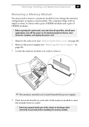
... close all open files, exit all open applications, turn off the power to all attached peripheral devices, shut down the computer, and unplug the power cord. 1 Remove the side cover (see "Removing the Side Cover" on page 28). 2 Remove the power supply (see "Removing the Power Supply" on page 50). 3 Locate the memory module you change the...
... close all open files, exit all open applications, turn off the power to all attached peripheral devices, shut down the computer, and unplug the power cord. 1 Remove the side cover (see "Removing the Side Cover" on page 28). 2 Remove the power supply (see "Removing the Power Supply" on page 50). 3 Locate the memory module you change the...
System Reference Manual
Page 60
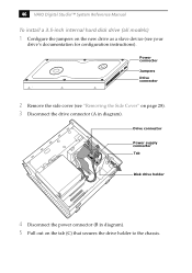
Power connector Jumpers Drive connector 2 Remove the side cover (see "Removing the Side Cover" on page 28). 3 Disconnect the drive connector (A in diagram). 5 Pull out on the new drive as a slave device (see your drive's documentation for configuration instructions). Drive connector A B C Power supply connector Tab Disk drive holder 4 Disconnect the power connector (B in diagram). 46 VAIO Digital Studio™ System Reference Manual To install a 3.5-inch internal hard disk drive (all models) 1 Configure the jumpers on the tab (C) that secures the drive holder to the chassis.
Power connector Jumpers Drive connector 2 Remove the side cover (see "Removing the Side Cover" on page 28). 3 Disconnect the drive connector (A in diagram). 5 Pull out on the new drive as a slave device (see your drive's documentation for configuration instructions). Drive connector A B C Power supply connector Tab Disk drive holder 4 Disconnect the power connector (B in diagram). 46 VAIO Digital Studio™ System Reference Manual To install a 3.5-inch internal hard disk drive (all models) 1 Configure the jumpers on the tab (C) that secures the drive holder to the chassis.
System Reference Manual
Page 64
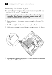
...). ! 50 VAIO Digital Studio™ System Reference Manual Removing the Power Supply You remove the power supply when you insert a memory module (see "Installing System Memory" on top of the chassis. 2 Pull the tab (A) that secures the power supply to the chassis. 3 Slide the power supply up until the power supply clears the chassis. A 4 Rotate the power supply upside down the computer, and unplug the power cord...
...). ! 50 VAIO Digital Studio™ System Reference Manual Removing the Power Supply You remove the power supply when you insert a memory module (see "Installing System Memory" on top of the chassis. 2 Pull the tab (A) that secures the power supply to the chassis. 3 Slide the power supply up until the power supply clears the chassis. A 4 Rotate the power supply upside down the computer, and unplug the power cord...

System Reference Manual
Page 65
Removing, Installing, and Replacing Components 51 Replacing the Power Supply 1 Rotate the power supply down and slide it down along the rails on each side of the chassis opening. 2 Replace the screw that secures the power supply to the rear of the chassis.
Removing, Installing, and Replacing Components 51 Replacing the Power Supply 1 Rotate the power supply down and slide it down along the rails on each side of the chassis opening. 2 Replace the screw that secures the power supply to the rear of the chassis.

System Reference Manual
Page 67
Chapter 4 System Board This chapter identifies each component on the system board and provides a detailed description of each header, connector, and jumper on the system board. Keyboard, Mouse Processor Memory CPU Fan Power Supply Fan USB1, USB2, Ethernet Serial, Printer, iLink 1394 Header 2 Game, Mic In, Line In, Line Out 1394 Header 3 Aux-In Video Aux Power Supply Power Supply Secondary IDE Primary IDE Diskette Slot 4 (AGP) Battery CD-In Slot No. 3 (PCI) Slot No. 2 (PCI) Slot No. 1 (PCI) CMOS Clear Front Panel Header USB23 Header 53
Chapter 4 System Board This chapter identifies each component on the system board and provides a detailed description of each header, connector, and jumper on the system board. Keyboard, Mouse Processor Memory CPU Fan Power Supply Fan USB1, USB2, Ethernet Serial, Printer, iLink 1394 Header 2 Game, Mic In, Line In, Line Out 1394 Header 3 Aux-In Video Aux Power Supply Power Supply Secondary IDE Primary IDE Diskette Slot 4 (AGP) Battery CD-In Slot No. 3 (PCI) Slot No. 2 (PCI) Slot No. 1 (PCI) CMOS Clear Front Panel Header USB23 Header 53
System Reference Manual
Page 74
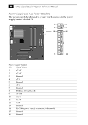
60 VAIO Digital Studio™ System Reference Manual Power Supply and Aux Power Headers The power supply header on the system board connects to the power supply header labelled P1. 2 4 1 3 10 20 1 11 Power Supply header Pin Signal Name 1 +3.3 V 2 +3.3 V 3 Ground 4 +5 V 5 Ground 6 +5 V 7 Ground 8 PWRGD (Power Good) 9 +5 VSB 10 +12 V 11 +3.3 V 12 -12 V 13 Ground 14 PS-ON# (power supply remote on/off control) 15 Ground 16 Ground
60 VAIO Digital Studio™ System Reference Manual Power Supply and Aux Power Headers The power supply header on the system board connects to the power supply header labelled P1. 2 4 1 3 10 20 1 11 Power Supply header Pin Signal Name 1 +3.3 V 2 +3.3 V 3 Ground 4 +5 V 5 Ground 6 +5 V 7 Ground 8 PWRGD (Power Good) 9 +5 VSB 10 +12 V 11 +3.3 V 12 -12 V 13 Ground 14 PS-ON# (power supply remote on/off control) 15 Ground 16 Ground

System Reference Manual
Page 75
Power Supply header (cont.) Pin Signal Name 17 Ground 18 No Connection 19 +5 V 20 +5 V Aux Power header Pin Signal Name 1 Ground 2 Ground 3 +12 V 4 +12 V System Board 61
Power Supply header (cont.) Pin Signal Name 17 Ground 18 No Connection 19 +5 V 20 +5 V Aux Power header Pin Signal Name 1 Ground 2 Ground 3 +12 V 4 +12 V System Board 61

System Reference Manual
Page 80
66 VAIO Digital Studio™ System Reference Manual The 6-pin i.LINK port on the back of the system can supply power from the computer to 12 V and a maximum power of 6 watts. 13 1 25 14 Printer 1 5 6 9 Serial i.LINK Serial port Pin Signal Name 1 DCD 2 RXD 3 TXD 4 DTR 5 LOGIC GND 6 DSR 7 RTS 8 CTS 9 RI The 6-pin port supplies 10 V to a device if the device also has a 6-pin port.
66 VAIO Digital Studio™ System Reference Manual The 6-pin i.LINK port on the back of the system can supply power from the computer to 12 V and a maximum power of 6 watts. 13 1 25 14 Printer 1 5 6 9 Serial i.LINK Serial port Pin Signal Name 1 DCD 2 RXD 3 TXD 4 DTR 5 LOGIC GND 6 DSR 7 RTS 8 CTS 9 RI The 6-pin port supplies 10 V to a device if the device also has a 6-pin port.
System Reference Manual
Page 83
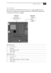
PWR-FAN controls the cooling fan in the power supply. CPU-FAN controls the cooling fan on the CPU. CPU-FAN 1 3 PWR-FAN 3 1 CPU-FAN header Pin Signal Name 1 Ground 2 FAN_CTRL (+12V) 3 FAN_SEN PWR-FAN header Pin Signal Name 1 Ground 2 FAN_CTRL [0 V(S3) , 2 V(S1), 12 V(S0)] 3 FAN_SEN System Board 69 Fan Headers The CPU-FAN and PWR-FAN headers are 1 x 3-pin straight headers.
PWR-FAN controls the cooling fan in the power supply. CPU-FAN controls the cooling fan on the CPU. CPU-FAN 1 3 PWR-FAN 3 1 CPU-FAN header Pin Signal Name 1 Ground 2 FAN_CTRL (+12V) 3 FAN_SEN PWR-FAN header Pin Signal Name 1 Ground 2 FAN_CTRL [0 V(S3) , 2 V(S1), 12 V(S0)] 3 FAN_SEN System Board 69 Fan Headers The CPU-FAN and PWR-FAN headers are 1 x 3-pin straight headers.
Marketing Specifications
Page 1
... Microphone Supplied Accessories Speakers VAIO Smart Keyboard PS/2 Wheel Mouse RJ-11 Phone Cord Power Cord Power Requirements 100-120V -3A (50/60Hz) Power Management ACPI 1.0 Compliant Advanced Power Management ...1394) chipset on the Sony Desktop Computer are NOT authorized to the performance of this product is a trademark of non-Sony products you and may ...sony.com/vaio Computer Interface: The computer industry lacks standards, and therefore, there are trademarks of varying software packages and add-on display. ©2001 Sony Electronics Inc. PCV-RX463DS Sony VAIO Digital Studio...
... Microphone Supplied Accessories Speakers VAIO Smart Keyboard PS/2 Wheel Mouse RJ-11 Phone Cord Power Cord Power Requirements 100-120V -3A (50/60Hz) Power Management ACPI 1.0 Compliant Advanced Power Management ...1394) chipset on the Sony Desktop Computer are NOT authorized to the performance of this product is a trademark of non-Sony products you and may ...sony.com/vaio Computer Interface: The computer industry lacks standards, and therefore, there are trademarks of varying software packages and add-on display. ©2001 Sony Electronics Inc. PCV-RX463DS Sony VAIO Digital Studio...


