
System Reference Manual
Page 2
...to software may require a fee and credit card information. Sony, VAIO, the VAIO logo, VAIO Digital Studio, and i.LINK are trademarks or registered trademarks of Sony. All other trademarks are trademarks of their respective owners. SONY ELECTRONICS INC. Software specifications are trademarks of a separate user... here. The software described herein is prohibited. This product contains software owned by Sony and licensed by the terms of Intel Corporation. Model Numbers: PCV-RX462DS/ PCV-RX463DS/PCV-RX465DS/ PCV-RX470DS/PCV-RX480DS/ PCV-RX490TV Serial Number ii
...to software may require a fee and credit card information. Sony, VAIO, the VAIO logo, VAIO Digital Studio, and i.LINK are trademarks or registered trademarks of Sony. All other trademarks are trademarks of their respective owners. SONY ELECTRONICS INC. Software specifications are trademarks of a separate user... here. The software described herein is prohibited. This product contains software owned by Sony and licensed by the terms of Intel Corporation. Model Numbers: PCV-RX462DS/ PCV-RX463DS/PCV-RX465DS/ PCV-RX470DS/PCV-RX480DS/ PCV-RX490TV Serial Number ii

System Reference Manual
Page 5
... augmente les risques pour les yeux. Adressez-vous à un agent de service qualifié. ! Operation is subject to Part 15 of Conformity Trade Name: SONY Model No.: PCV-RX462DS PCV-RX463DS PCV-RX465DS PCV-RX470DS PCV-RX480DS PCV-RX490TV Responsible Party: Sony Electronics Inc. Danger : Radiation laser visible et invisible si ouvert. Évitez l'exposition directe au faisceau...
... augmente les risques pour les yeux. Adressez-vous à un agent de service qualifié. ! Operation is subject to Part 15 of Conformity Trade Name: SONY Model No.: PCV-RX462DS PCV-RX463DS PCV-RX465DS PCV-RX470DS PCV-RX480DS PCV-RX490TV Responsible Party: Sony Electronics Inc. Danger : Radiation laser visible et invisible si ouvert. Évitez l'exposition directe au faisceau...

System Reference Manual
Page 12
... 3.5-inch Internal Hard Disk Drive 45 To prepare a startup disk (PCV-RX490TV model only 45 To install a 3.5-inch internal hard disk drive (all models 46 To set up the new hard drive with the startup disk (PCV-RX490TV model only 49 To identify the additional hard disk space for Giga Pocket ...use (PCV-RX490TV model only 49 Removing the Power Supply 50 Replacing the Power Supply 51 Chapter 4 - xii VAIO Digital Studio™ System Reference Manual Chapter 3 -...
... 3.5-inch Internal Hard Disk Drive 45 To prepare a startup disk (PCV-RX490TV model only 45 To install a 3.5-inch internal hard disk drive (all models 46 To set up the new hard drive with the startup disk (PCV-RX490TV model only 49 To identify the additional hard disk space for Giga Pocket ...use (PCV-RX490TV model only 49 Removing the Power Supply 50 Replacing the Power Supply 51 Chapter 4 - xii VAIO Digital Studio™ System Reference Manual Chapter 3 -...

System Reference Manual
Page 16
2 VAIO Digital Studio™ System Reference Manual Front View All Models
2 VAIO Digital Studio™ System Reference Manual Front View All Models
System Reference Manual
Page 20
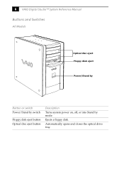
Ejects a floppy disk. Automatically opens and closes the optical drive tray. 6 VAIO Digital Studio™ System Reference Manual Buttons and Switches All Models Optical disc eject Floppy disk eject Power/Stand by Button or switch Power/Stand by switch Floppy disk eject button Optical disc eject button Description Turns system power on, off, or into Stand by mode.
Ejects a floppy disk. Automatically opens and closes the optical drive tray. 6 VAIO Digital Studio™ System Reference Manual Buttons and Switches All Models Optical disc eject Floppy disk eject Power/Stand by Button or switch Power/Stand by switch Floppy disk eject button Optical disc eject button Description Turns system power on, off, or into Stand by mode.

System Reference Manual
Page 21
... disk drive activity. On (blue) indicates the computer is turned off, or in Stand by mode. On (red) indicates hard disk drive activity. Indicators All Models Identifying Components 7 Floppy disk drive access Hard disk drive access Optical disc drive access Power/Stand by Indicator Power/Stand by indicator Floppy disk drive...
... disk drive activity. On (blue) indicates the computer is turned off, or in Stand by mode. On (red) indicates hard disk drive activity. Indicators All Models Identifying Components 7 Floppy disk drive access Hard disk drive access Optical disc drive access Power/Stand by Indicator Power/Stand by indicator Floppy disk drive...

System Reference Manual
Page 24
10 VAIO Digital Studio™ System Reference Manual Rear View All Models Mouse Keyboard USB1, USB2 Ethernet Serial Printer /Parallel i.LINK (IEEE394) Game/MIDI Headphones Line In Microphone Monitor Audio Out Video/S-video Out* Audio In Video/S-Video In* Line Power DVI VHF/UHF* Telephone** *Only in PCV-RX490TV Model ** In models with an HPNA modem, the telephone line jack does not exist.
10 VAIO Digital Studio™ System Reference Manual Rear View All Models Mouse Keyboard USB1, USB2 Ethernet Serial Printer /Parallel i.LINK (IEEE394) Game/MIDI Headphones Line In Microphone Monitor Audio Out Video/S-video Out* Audio In Video/S-Video In* Line Power DVI VHF/UHF* Telephone** *Only in PCV-RX490TV Model ** In models with an HPNA modem, the telephone line jack does not exist.

System Reference Manual
Page 25
Icons All Models Identifying Components 11 Icon Label Area All Models Icon Description Mouse port Keyboard port Universal Serial Bus (USB) port Ethernet port (for LAN connection only) Serial port Printer port i.LINK (IEEE1394) port Game/MIDI port
Icons All Models Identifying Components 11 Icon Label Area All Models Icon Description Mouse port Keyboard port Universal Serial Bus (USB) port Ethernet port (for LAN connection only) Serial port Printer port i.LINK (IEEE1394) port Game/MIDI port

System Reference Manual
Page 26
12 VAIO Digital Studio™ System Reference Manual All Models Icon Description Headphones LINE IN jack (audio) Microphone jack Monitor port Line jack (for telephone line from primary service jack) Telephone jack (for phone)* DVI (LCD) Monitor port * In models with an HPNA modem, the telephone jack does not exist. PCV-RX490TV Only Icon Description VHF/UHF port Audio In jack Audio Out jack Video/S-video In port Video/S-video Out port
12 VAIO Digital Studio™ System Reference Manual All Models Icon Description Headphones LINE IN jack (audio) Microphone jack Monitor port Line jack (for telephone line from primary service jack) Telephone jack (for phone)* DVI (LCD) Monitor port * In models with an HPNA modem, the telephone jack does not exist. PCV-RX490TV Only Icon Description VHF/UHF port Audio In jack Audio Out jack Video/S-video In port Video/S-video Out port
System Reference Manual
Page 32
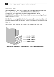
18 VAIO Digital Studio™ System Reference Manual Expansion Slots There are three PCI slots, two of which is occupied by an AGP card. PCI slot No. 1 .../modem card. Slot No. 4 (AGP) Slot No. 3 (PCI) Slot No. 2 (PCI)* Slot No. 1 (PCI) *Slot No. 2 is occupied by a Giga Pocket card in the PCV-RX462DS/PCV-RX463DS/ PCV-RX465DS/PCV-RX470DS/PCV-RX480DS models. In the PCV-RX490TV model, slot No. 3 is one jack (Line In). There is available for expansion (slot No. 2 and slot No. 3), in the...
18 VAIO Digital Studio™ System Reference Manual Expansion Slots There are three PCI slots, two of which is occupied by an AGP card. PCI slot No. 1 .../modem card. Slot No. 4 (AGP) Slot No. 3 (PCI) Slot No. 2 (PCI)* Slot No. 1 (PCI) *Slot No. 2 is occupied by a Giga Pocket card in the PCV-RX462DS/PCV-RX463DS/ PCV-RX465DS/PCV-RX470DS/PCV-RX480DS models. In the PCV-RX490TV model, slot No. 3 is one jack (Line In). There is available for expansion (slot No. 2 and slot No. 3), in the...

System Reference Manual
Page 41
Chapter 3 Removing, Installing, and Replacing Components This chapter describes removing, installing, and replacing major components for upgrading, reconfiguring, and troubleshooting the components. ! Before opening the system unit, save and close all open files, exit all open applications, turn off the power to all attached peripheral devices, shut down the computer, and unplug the power cord. ✍ Systems differ by model, so your system may appear different from the illustrations in this chapter. 27
Chapter 3 Removing, Installing, and Replacing Components This chapter describes removing, installing, and replacing major components for upgrading, reconfiguring, and troubleshooting the components. ! Before opening the system unit, save and close all open files, exit all open applications, turn off the power to all attached peripheral devices, shut down the computer, and unplug the power cord. ✍ Systems differ by model, so your system may appear different from the illustrations in this chapter. 27

System Reference Manual
Page 51
Memory module configurations (MB)* RIMM1 RIMM2 0, 8, 16, 32, 64, 128, 256 0, 8, 16, 32, 64, 128, 256 * All models ship with either bank empty. Do not leave the second slot of either RIMM or CRIMM modules. 2 If necessary, remove the memory module you purchased it through the VAIO Direct Web site. ✍ Use...unplug the power cord. 1 Choose the size of the memory modules. Memory modules can vary in pairs. RIMM memory is 512 MB. Your model may ship with more than 128 MB of RIMM™ memory if you wish to replace (see "Removing the Power Supply" on page 50). 6 Remove the screw...
Memory module configurations (MB)* RIMM1 RIMM2 0, 8, 16, 32, 64, 128, 256 0, 8, 16, 32, 64, 128, 256 * All models ship with either bank empty. Do not leave the second slot of either RIMM or CRIMM modules. 2 If necessary, remove the memory module you purchased it through the VAIO Direct Web site. ✍ Use...unplug the power cord. 1 Choose the size of the memory modules. Memory modules can vary in pairs. RIMM memory is 512 MB. Your model may ship with more than 128 MB of RIMM™ memory if you wish to replace (see "Removing the Power Supply" on page 50). 6 Remove the screw...

System Reference Manual
Page 52
38 VAIO Digital Studio™ System Reference Manual 8 Remove the AGP add-in card. ✍ Grasp the card with one hand on each end, and gently pull up as you rock the card from side to discharge any components or contacts on the card. Static electricity in the PCV-RX490TV model. 9 Align the module...
38 VAIO Digital Studio™ System Reference Manual 8 Remove the AGP add-in card. ✍ Grasp the card with one hand on each end, and gently pull up as you rock the card from side to discharge any components or contacts on the card. Static electricity in the PCV-RX490TV model. 9 Align the module...
System Reference Manual
Page 59
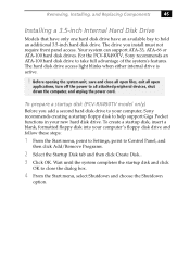
... save and close the dialog box. 4 From the Start menu, select Shutdown and choose the Shutdown option. To prepare a startup disk (PCV-RX490TV model only) Before you install must not require front panel access. To create a startup disk, insert a blank, formatted floppy disk into your ... the Startup Disk tab and then click Create Disk... 3 Click OK. The drive you add a second hard disk drive to your computer, Sony recommends creating a startup floppy disk to hold an additional 3.5-inch hard disk drive. Removing, Installing, and Replacing Components 45 Installing a 3.5-inch Internal...
... save and close the dialog box. 4 From the Start menu, select Shutdown and choose the Shutdown option. To prepare a startup disk (PCV-RX490TV model only) Before you install must not require front panel access. To create a startup disk, insert a blank, formatted floppy disk into your ... the Startup Disk tab and then click Create Disk... 3 Click OK. The drive you add a second hard disk drive to your computer, Sony recommends creating a startup floppy disk to hold an additional 3.5-inch hard disk drive. Removing, Installing, and Replacing Components 45 Installing a 3.5-inch Internal...
System Reference Manual
Page 60
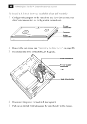
Power connector Jumpers Drive connector 2 Remove the side cover (see "Removing the Side Cover" on page 28). 3 Disconnect the drive connector (A in diagram). 5 Pull out on the new drive as a slave device (see your drive's documentation for configuration instructions). Drive connector A B C Power supply connector Tab Disk drive holder 4 Disconnect the power connector (B in diagram). 46 VAIO Digital Studio™ System Reference Manual To install a 3.5-inch internal hard disk drive (all models) 1 Configure the jumpers on the tab (C) that secures the drive holder to the chassis.
Power connector Jumpers Drive connector 2 Remove the side cover (see "Removing the Side Cover" on page 28). 3 Disconnect the drive connector (A in diagram). 5 Pull out on the new drive as a slave device (see your drive's documentation for configuration instructions). Drive connector A B C Power supply connector Tab Disk drive holder 4 Disconnect the power connector (B in diagram). 46 VAIO Digital Studio™ System Reference Manual To install a 3.5-inch internal hard disk drive (all models) 1 Configure the jumpers on the tab (C) that secures the drive holder to the chassis.

System Reference Manual
Page 62
Do not complete step 16 of this procedure; All models except the PCV-RX490TV will automatically recognize the new drive and configure itself accordingly when you turn on your new hard drive. Drive connectors C E B D Power connectors Tab A Disk ... page 29). ! Format and partition the new drive following page to the chassis. it on. For the PCV-RX490TV model, refer to the instructions on the following the instructions provided with the drive. 48 VAIO Digital Studio™ System Reference Manual 10 Push in on the tab (A) to securely latch the holder to...
Do not complete step 16 of this procedure; All models except the PCV-RX490TV will automatically recognize the new drive and configure itself accordingly when you turn on your new hard drive. Drive connectors C E B D Power connectors Tab A Disk ... page 29). ! Format and partition the new drive following page to the chassis. it on. For the PCV-RX490TV model, refer to the instructions on the following the instructions provided with the drive. 48 VAIO Digital Studio™ System Reference Manual 10 Push in on the tab (A) to securely latch the holder to...
System Reference Manual
Page 63
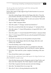
... startup. 3 Type in "2" and press Enter. 6 Select the option "1. To identify the additional hard disk space for Giga Pocket use (PCV-RX490TV model only) 1 From the Start menu, point to Programs, point to Giga Pocket, and then click Video Explorer. Create DOS partition or Logical DOS...menu appears. 2 Select the option "4. Removing, Installing, and Replacing Components 49 To set up the new hard drive with the startup disk (PCV-RX490TV model only) Follow these steps to help support Giga Pocket functions in the Extended DOS Partition" and press Enter. 9 Specify the maximum size for...
... startup. 3 Type in "2" and press Enter. 6 Select the option "1. To identify the additional hard disk space for Giga Pocket use (PCV-RX490TV model only) 1 From the Start menu, point to Programs, point to Giga Pocket, and then click Video Explorer. Create DOS partition or Logical DOS...menu appears. 2 Select the option "4. Removing, Installing, and Replacing Components 49 To set up the new hard drive with the startup disk (PCV-RX490TV model only) Follow these steps to help support Giga Pocket functions in the Extended DOS Partition" and press Enter. 9 Specify the maximum size for...

System Reference Manual
Page 71
... card. The PCI slots support 32-bit 5 V and Universal (3.3/5 V) PCI add-in cards. In models PCV-RX462DS/PCV-RX463DS/PCV-RX465DS/ PCV-RX470DS/PCV-RX480DS, PCI slot No. 2 and No. 3 are a total of three PCI slots (slot No. 1 to No. 3). In all models, PCI slot No. 1 is available for expansion. Your modem may look different depending on whether...
... card. The PCI slots support 32-bit 5 V and Universal (3.3/5 V) PCI add-in cards. In models PCV-RX462DS/PCV-RX463DS/PCV-RX465DS/ PCV-RX470DS/PCV-RX480DS, PCI slot No. 2 and No. 3 are a total of three PCI slots (slot No. 1 to No. 3). In all models, PCI slot No. 1 is available for expansion. Your modem may look different depending on whether...

System Reference Manual
Page 95
Chapter 6 Giga Pocket Card The Giga Pocket card occupies PCI slot No. 2 in the PCV-RX490TV model. VHF/UHF Port Audio In Jack Video/S-video In Port Audio Out Jack Video/S-video Out Port Connector Description CN1 CN2 Pin1 Ground Ground Pin2 L-Out Ground CN3 Ground CN4 Ground L-In Ground CN5 CN8 CN9 L-Out L-Out Reserved (ID) L-Out L-Out Reserved (ID2) Pin3 R-Out Y-Out Pin4 C-Out R-In Y-In C-In Ground Ground Y-In (Front) R-Out R-Out C-In (Front) Pin5 Reserved (ID) Reserved (ID) Ground 81 The Giga Pocket card has seven connectors and ten pins.
Chapter 6 Giga Pocket Card The Giga Pocket card occupies PCI slot No. 2 in the PCV-RX490TV model. VHF/UHF Port Audio In Jack Video/S-video In Port Audio Out Jack Video/S-video Out Port Connector Description CN1 CN2 Pin1 Ground Ground Pin2 L-Out Ground CN3 Ground CN4 Ground L-In Ground CN5 CN8 CN9 L-Out L-Out Reserved (ID) L-Out L-Out Reserved (ID2) Pin3 R-Out Y-Out Pin4 C-Out R-In Y-In C-In Ground Ground Y-In (Front) R-Out R-Out C-In (Front) Pin5 Reserved (ID) Reserved (ID) Ground 81 The Giga Pocket card has seven connectors and ten pins.

System Reference Manual
Page 101
CMOS Setup Options 87 Main Screen System Time [00:00:00] System Date [01/01/2001] Primary Master (see "IDE Sub-Menus" on page 88) Primary Slave (see "IDE Sub-Menus" on page 88) Secondary Master (see "IDE Sub-Menus" on page 88) Secondary Slave (see "IDE Sub-Menus" on page 88) Supervisor Password [Disabled] User Password [Disabled] Installed Memory 128 MB BIOS Revision/Version 1002 (depends on model)
CMOS Setup Options 87 Main Screen System Time [00:00:00] System Date [01/01/2001] Primary Master (see "IDE Sub-Menus" on page 88) Primary Slave (see "IDE Sub-Menus" on page 88) Secondary Master (see "IDE Sub-Menus" on page 88) Secondary Slave (see "IDE Sub-Menus" on page 88) Supervisor Password [Disabled] User Password [Disabled] Installed Memory 128 MB BIOS Revision/Version 1002 (depends on model)


