User Guide
Page 28
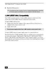
... total power supplied by contacting Sony at http:/ /www.sony.com/accessories. 28 Sony computer supplies, accessories, and peripherals can : ❑ supply power from your computer: VMC-IL4415, VMC-IL4435, VMC-IL4615, VMCIL4635, VMC-IL6615, and VMC-IL6635. The following Sony i.LINK 400 Mbps cables are available and recommended for use with a 6-pin connector, and ❑ supply 10V to 12V. ! VAIO Digital Studio™ Computer User...
... total power supplied by contacting Sony at http:/ /www.sony.com/accessories. 28 Sony computer supplies, accessories, and peripherals can : ❑ supply power from your computer: VMC-IL4415, VMC-IL4435, VMC-IL4615, VMCIL4635, VMC-IL6615, and VMC-IL6635. The following Sony i.LINK 400 Mbps cables are available and recommended for use with a 6-pin connector, and ❑ supply 10V to 12V. ! VAIO Digital Studio™ Computer User...
User Guide
Page 34
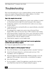
...VAIO Digital Studio™ Computer User Guide Troubleshooting This section describes how to solve common problems you may encounter when using a bootable diskette). ❑ Confirm that the power cord and all cables are connected firmly, as described on the color poster. ❑ If you plugged the computer into a power strip or Universal Power Supply... you call Sony Customer Support. Many problems have simple solutions, so try these suggestions before you are adjusted correctly. Topic: My computer does not start. ❑ Check that the computer is plugged into a power source and ...
...VAIO Digital Studio™ Computer User Guide Troubleshooting This section describes how to solve common problems you may encounter when using a bootable diskette). ❑ Confirm that the power cord and all cables are connected firmly, as described on the color poster. ❑ If you plugged the computer into a power strip or Universal Power Supply... you call Sony Customer Support. Many problems have simple solutions, so try these suggestions before you are adjusted correctly. Topic: My computer does not start. ❑ Check that the computer is plugged into a power source and ...

User Guide
Page 45
...To Reach Sony For further assistance, call 1-888-4SONYPC (1-888-476-6972). If you are operating this computer outside of shortcuts. 5 Click Microsoft Find Fast. 6 Click the Remove button. 7 Click Close. 8 Click OK. The system is designed to provide 2 amps (average) of 5V power for the power supply. Notes on...add components to Find Fast. If you notice that the local AC specifications match before plugging in the computer. ❑ The total power draw of 10 amps. The total from the power supply, the maximum combined +3.3V and +5V output must not exceed 10 amps. Notes on Use On...
...To Reach Sony For further assistance, call 1-888-4SONYPC (1-888-476-6972). If you are operating this computer outside of shortcuts. 5 Click Microsoft Find Fast. 6 Click the Remove button. 7 Click Close. 8 Click OK. The system is designed to provide 2 amps (average) of 5V power for the power supply. Notes on...add components to Find Fast. If you notice that the local AC specifications match before plugging in the computer. ❑ The total power draw of 10 amps. The total from the power supply, the maximum combined +3.3V and +5V output must not exceed 10 amps. Notes on Use On...

User Guide
Page 46
... copying machines or shredders. ❑ You can purchase a power strip with the cover removed. The battery backup safeguards your computer caused by sudden power surges such as described in the power supply. VAIO Digital Studio™ Computer User Guide ❑ Plug all the power cords for your equipment, refer the repair or replacement of the power supply to qualified personnel only. 46
... copying machines or shredders. ❑ You can purchase a power strip with the cover removed. The battery backup safeguards your computer caused by sudden power surges such as described in the power supply. VAIO Digital Studio™ Computer User Guide ❑ Plug all the power cords for your equipment, refer the repair or replacement of the power supply to qualified personnel only. 46
User Guide
Page 62
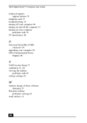
VAIO Digital Studio™ Computer User Guide technical support support options 51 telephone jack 15 troubleshooting 34 turning off your computer 46 turning on and off the computer 13 turning on your computer problems with 34 TV interference 48 U Universal Serial Bus (USB) connector 16 upgrading your computer 48 UPS (Uninterrupted Power Supply) 46 V VAIO Action Setup 17 ventilation 11, 48 viewing the taskbar problems with 42 voltage settings 45 W window design of Sony software changing 19 Windows taskbar problems viewing 42 work surfaces 11 62
VAIO Digital Studio™ Computer User Guide technical support support options 51 telephone jack 15 troubleshooting 34 turning off your computer 46 turning on and off the computer 13 turning on your computer problems with 34 TV interference 48 U Universal Serial Bus (USB) connector 16 upgrading your computer 48 UPS (Uninterrupted Power Supply) 46 V VAIO Action Setup 17 ventilation 11, 48 viewing the taskbar problems with 42 voltage settings 45 W window design of Sony software changing 19 Windows taskbar problems viewing 42 work surfaces 11 62

Reference Manual
Page 12
xii VAIO Digital Studio™ Reference Manual Chapter 3 - Removing, Installing, and Replacing Components Removing the Cover 22 Removing the Front Panel 24 Replacing the Front Panel 25 Replacing the ... 34 Removing a Memory Module 37 Removing a Slot Cover 39 Covering an Open I/O Slot 40 Installing a 3½" Internal Hard Disk Drive 41 Removing the Power Supply 45 Replacing the Power Supply 48 Chapter 4 - System Board Connectors 50 Front Panel Header (J25 50 Diskette Drive Connector 51 Memory Module (DIMM) Connectors 52 PCI Slot Connectors 53...
xii VAIO Digital Studio™ Reference Manual Chapter 3 - Removing, Installing, and Replacing Components Removing the Cover 22 Removing the Front Panel 24 Replacing the Front Panel 25 Replacing the ... 34 Removing a Memory Module 37 Removing a Slot Cover 39 Covering an Open I/O Slot 40 Installing a 3½" Internal Hard Disk Drive 41 Removing the Power Supply 45 Replacing the Power Supply 48 Chapter 4 - System Board Connectors 50 Front Panel Header (J25 50 Diskette Drive Connector 51 Memory Module (DIMM) Connectors 52 PCI Slot Connectors 53...
Reference Manual
Page 36
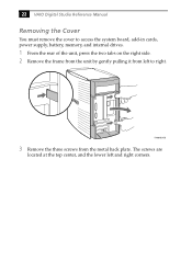
KY0064B.VSD 3 Remove the three screws from left and right corners. The screws are located at the top center, and the lower left to access the system board, add-in cards, power supply, battery, memory, and internal drives. 1 From the rear of the unit, press the two tabs on the right side. 2 Remove the frame from the unit by gently pulling it from the metal back plate. 22 VAIO Digital Studio Reference Manual Removing the Cover You must remove the cover to right.
KY0064B.VSD 3 Remove the three screws from left and right corners. The screws are located at the top center, and the lower left to access the system board, add-in cards, power supply, battery, memory, and internal drives. 1 From the rear of the unit, press the two tabs on the right side. 2 Remove the frame from the unit by gently pulling it from the metal back plate. 22 VAIO Digital Studio Reference Manual Removing the Cover You must remove the cover to right.

Reference Manual
Page 43
Before opening the system unit, save any open files, exit Windows, turn off the power of the computer and all attached peripherals, and then unplug the power cord. 1 Remove the cover (see "Removing the Cover" on page 22). 2 Disconnect any components or connector contacts on the card. Static electricity in your body ..., Installing, and Replacing Components 29 Removing an Add-in card from side to side. ! KY0071.VSD ✍ Grasp the card with one hand on the power supply) before handling an add-in card to discharge any static electricity in your body.
Before opening the system unit, save any open files, exit Windows, turn off the power of the computer and all attached peripherals, and then unplug the power cord. 1 Remove the cover (see "Removing the Cover" on page 22). 2 Disconnect any components or connector contacts on the card. Static electricity in your body ..., Installing, and Replacing Components 29 Removing an Add-in card from side to side. ! KY0071.VSD ✍ Grasp the card with one hand on the power supply) before handling an add-in card to discharge any static electricity in your body.

Reference Manual
Page 48
... * The PCV-R556DS/PCV-R558DS ships with 133 MHz memory. SDRAM is expandable to replace (see "Removing a Memory Module" on page 37). 2 Remove the new memory module(s) from the computer. 5 Remove the cover (see "Removing the Cover" on page 22). 6 Remove the power supply (see "Removing the Power Supply" on page 45). Supports SDRAM memory. 34 VAIO Digital Studio Reference Manual...
... * The PCV-R556DS/PCV-R558DS ships with 133 MHz memory. SDRAM is expandable to replace (see "Removing a Memory Module" on page 37). 2 Remove the new memory module(s) from the computer. 5 Remove the cover (see "Removing the Cover" on page 22). 6 Remove the power supply (see "Removing the Power Supply" on page 45). Supports SDRAM memory. 34 VAIO Digital Studio Reference Manual...

Reference Manual
Page 49
If the handles are straight up and locked into place. 10 Replace the power supply (see "Replacing the Power Supply" on page 48). 11 Replace the cover (see "Replacing the Cover" on each side are not totally straight upright, continue to press down firmly and ...
If the handles are straight up and locked into place. 10 Replace the power supply (see "Replacing the Power Supply" on page 48). 11 Replace the cover (see "Replacing the Cover" on each side are not totally straight upright, continue to press down firmly and ...

Reference Manual
Page 51
...power of the computer and all attached peripherals, and then unplug the power cord. 13 Remove the cover (see "Removing the Cover" on page 22). 14 Locate the memory module you change the memory configuration or replace a bad module. ! KY0073.VSD ✍ The memory modules are located beneath the power supply.... You do not need to remove a memory module if you wish to reach the memory modules. Removing, Installing, and Replacing Components 37 Removing a Memory Module You may need to remove the power supply to remove.
...power of the computer and all attached peripherals, and then unplug the power cord. 13 Remove the cover (see "Removing the Cover" on page 22). 14 Locate the memory module you change the memory configuration or replace a bad module. ! KY0073.VSD ✍ The memory modules are located beneath the power supply.... You do not need to remove a memory module if you wish to reach the memory modules. Removing, Installing, and Replacing Components 37 Removing a Memory Module You may need to remove the power supply to remove.

Reference Manual
Page 52
Store the module in your body before handling the memory module. 38 VAIO Digital Studio Reference Manual 15 Reach around each side of the power supply and push down the handle on each side of the chassis to eject the module from its socket. Touch any exposed metal part of the memory module to discharge static electricity in a static-free bag. ! Push out Handles KY00 16 Grasp one edge of the memory module and lift out.
Store the module in your body before handling the memory module. 38 VAIO Digital Studio Reference Manual 15 Reach around each side of the power supply and push down the handle on each side of the chassis to eject the module from its socket. Touch any exposed metal part of the memory module to discharge static electricity in a static-free bag. ! Push out Handles KY00 16 Grasp one edge of the memory module and lift out.

Reference Manual
Page 56
A A A A Disk drive holder B KY0081.VSD 6 Place the drive holder on top of the power supply. 7 Slide the new drive into the drive holder and align the holes on each side of the drive holder (screws are provided with the new drive). Align holes KY0083.VSD 8 Secure the drive to the new drive (see next diagram). Do not overtighten the screws. 9 Connect the second drive connector to the drive holder using the two holes on each side of the drive holder. 42 VAIO Digital Studio Reference Manual 5 Slide the drive holder forward (B), and then out.
A A A A Disk drive holder B KY0081.VSD 6 Place the drive holder on top of the power supply. 7 Slide the new drive into the drive holder and align the holes on each side of the drive holder (screws are provided with the new drive). Align holes KY0083.VSD 8 Secure the drive to the new drive (see next diagram). Do not overtighten the screws. 9 Connect the second drive connector to the drive holder using the two holes on each side of the drive holder. 42 VAIO Digital Studio Reference Manual 5 Slide the drive holder forward (B), and then out.

Reference Manual
Page 59
Removing, Installing, and Replacing Components 45 Removing the Power Supply You remove the power supply when you insert a memory module (see "Installing System Memory" on page 34). 1 Remove the three screws (A in next diagram) from the rear of the chassis. 2 Remove the screw (B) from the power supply bracket. A B KY0096.VSD
Removing, Installing, and Replacing Components 45 Removing the Power Supply You remove the power supply when you insert a memory module (see "Installing System Memory" on page 34). 1 Remove the three screws (A in next diagram) from the rear of the chassis. 2 Remove the screw (B) from the power supply bracket. A B KY0096.VSD

Reference Manual
Page 60
KY0097.VSD 46 VAIO Digital Studio Reference Manual 3 Slide the power supply back (towards the 3½" drive bay) about ½" (or until the power supply detaches from the chassis tabs), then lift up until the power supply clears the chassis lip.
KY0097.VSD 46 VAIO Digital Studio Reference Manual 3 Slide the power supply back (towards the 3½" drive bay) about ½" (or until the power supply detaches from the chassis tabs), then lift up until the power supply clears the chassis lip.

Reference Manual
Page 61
Removing, Installing, and Replacing Components 47 4 Rotate the power supply horizontally by 180 degrees counterclockwise and rest it on top of the chassis where the CDROM/DVD-ROM drive is located. KY0098.VSD
Removing, Installing, and Replacing Components 47 4 Rotate the power supply horizontally by 180 degrees counterclockwise and rest it on top of the chassis where the CDROM/DVD-ROM drive is located. KY0098.VSD
Reference Manual
Page 62
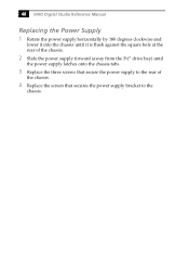
48 VAIO Digital Studio Reference Manual Replacing the Power Supply 1 Rotate the power supply horizontally by 180 degrees clockwise and lower it into the chassis until it is flush against the square hole at the rear of the chassis. 2 Slide the power supply forward (away from the 3½" drive bay) until the power supply latches onto the chassis tabs. 3 Replace the three screws that secure the power supply to the rear of the chassis. 4 Replace the screen that secures the power supply bracket to the chassis.
48 VAIO Digital Studio Reference Manual Replacing the Power Supply 1 Rotate the power supply horizontally by 180 degrees clockwise and lower it into the chassis until it is flush against the square hole at the rear of the chassis. 2 Slide the power supply forward (away from the 3½" drive bay) until the power supply latches onto the chassis tabs. 3 Replace the three screws that secure the power supply to the rear of the chassis. 4 Replace the screen that secures the power supply bracket to the chassis.

Reference Manual
Page 63
Keyboard, Mouse USB1, USB2, Ethernet COM1, Printer, i.LINK 1394 Header 2 Game Mic In, Line In, Line Out 1394 Header 3 CD-In Video Aux-In Processor CPU Fan Memory Slot 3 (PCI) Slot 2 (PCI) Slot 1 (PCI) Power Supply Fan Power Supply Secondary IDE Primary IDE Diskette AGP USB2 Header Battery Configuration Jumpers Front panel header OM04581.VSD 49 Chapter 4 System Board This chapter identifies each component on the system board and provides a detailed description of each connector, jumper, and switch on the system board.
Keyboard, Mouse USB1, USB2, Ethernet COM1, Printer, i.LINK 1394 Header 2 Game Mic In, Line In, Line Out 1394 Header 3 CD-In Video Aux-In Processor CPU Fan Memory Slot 3 (PCI) Slot 2 (PCI) Slot 1 (PCI) Power Supply Fan Power Supply Secondary IDE Primary IDE Diskette AGP USB2 Header Battery Configuration Jumpers Front panel header OM04581.VSD 49 Chapter 4 System Board This chapter identifies each component on the system board and provides a detailed description of each connector, jumper, and switch on the system board.

Reference Manual
Page 69
Each IDE connector supports up to two IDE drives using a ribbon cable with two connectors. 40 39 2 1 OM04701G.VSD Power Connector The power supply connector on the system board: a Primary IDE and a Secondary IDE connector. System Board 55 IDE Connectors There are two IDE (Integrated Drive Electronics) connectors on the system board connects to the power supply connector labelled P1. 10 20 1 11 OM04701I.VSD
Each IDE connector supports up to two IDE drives using a ribbon cable with two connectors. 40 39 2 1 OM04701G.VSD Power Connector The power supply connector on the system board: a Primary IDE and a Secondary IDE connector. System Board 55 IDE Connectors There are two IDE (Integrated Drive Electronics) connectors on the system board connects to the power supply connector labelled P1. 10 20 1 11 OM04701I.VSD

Reference Manual
Page 75
PWR-FAN controls the cooling fan in the power supply. CPU-FAN 3 1 PWR FAN 3 1 CPU-FAN and PWR-FAN connectors Pin Signal Name 1 Ground 2 FAN_CTRL (+12V) 3 FAN_SEN KY0034.VSD System Board 61 i.LINK connector Pin Signal Name 1 Ground VP (Power)* 2 Ground 3 TPB* 4 TPB 5 TPA* 6 Ground TPA * Uses over-current protector. CPU-FAN controls the cooling fan on the CPU. Fan Connectors The CPU-FAN and PWR-FAN connectors are 1 x 3-pin straight header connectors.
PWR-FAN controls the cooling fan in the power supply. CPU-FAN 3 1 PWR FAN 3 1 CPU-FAN and PWR-FAN connectors Pin Signal Name 1 Ground 2 FAN_CTRL (+12V) 3 FAN_SEN KY0034.VSD System Board 61 i.LINK connector Pin Signal Name 1 Ground VP (Power)* 2 Ground 3 TPB* 4 TPB 5 TPA* 6 Ground TPA * Uses over-current protector. CPU-FAN controls the cooling fan on the CPU. Fan Connectors The CPU-FAN and PWR-FAN connectors are 1 x 3-pin straight header connectors.


