
System Reference Manual
Page 3
... the backup battery, contact your desktop to qualified personnel only. ! Refer servicing to rain or moisture. Visible and invisible laser radiation when open . iii VAIO Slimtop™ System Reference Manual Safety Information and Caution CD-RW/DVD Combo Drive Laser Diode Properties Laser Output (CD-RW) 1.08 mW (Read... The use only No. 26 AWG or larger telecommunication line cord. Danger - To avoid electrical shock, do not expose your nearest Sony Service Center. ! As the laser beam used in the vicinity of fire, use of optical instruments with this product is harmful to...
... the backup battery, contact your desktop to qualified personnel only. ! Refer servicing to rain or moisture. Visible and invisible laser radiation when open . iii VAIO Slimtop™ System Reference Manual Safety Information and Caution CD-RW/DVD Combo Drive Laser Diode Properties Laser Output (CD-RW) 1.08 mW (Read... The use only No. 26 AWG or larger telecommunication line cord. Danger - To avoid electrical shock, do not expose your nearest Sony Service Center. ! As the laser beam used in the vicinity of fire, use of optical instruments with this product is harmful to...

System Reference Manual
Page 12
...Installing System Memory 35 Removing a Memory Module 37 Replacing the Hard Drive 39 Removing a Slot Cover 42 Covering an Open I/O Slot 43 Chapter 4 - Fax/Modem Card xii VAIO Slimtop™ System Reference Manual Chapter 3 - System Board Connectors 46 Front Panel Header 46 IDE Connectors 47 PCI Slot ...VGA MONITOR Connector 53 LCD Connector 54 Wake On LAN (WOL_CON) Connector 55 PHONES, LINE IN, and MIC Connectors 56 Sony Memory Stick Media Slot Connector 57 i.LINK Interface Header Connectors 57 i.LINK Connectors 59 CD-In Connector 60 Configuration Switches 61 Chapter 5 -
...Installing System Memory 35 Removing a Memory Module 37 Replacing the Hard Drive 39 Removing a Slot Cover 42 Covering an Open I/O Slot 43 Chapter 4 - Fax/Modem Card xii VAIO Slimtop™ System Reference Manual Chapter 3 - System Board Connectors 46 Front Panel Header 46 IDE Connectors 47 PCI Slot ...VGA MONITOR Connector 53 LCD Connector 54 Wake On LAN (WOL_CON) Connector 55 PHONES, LINE IN, and MIC Connectors 56 Sony Memory Stick Media Slot Connector 57 i.LINK Interface Header Connectors 57 i.LINK Connectors 59 CD-In Connector 60 Configuration Switches 61 Chapter 5 -

System Reference Manual
Page 18
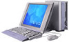
4 VAIO Slimtop™ System Reference Manual Buttons and Switches CD-RW/DVD combo drive disc eject PC card eject Power on/off Button or switch Power/Stand by switch CD-RW/DVD combo drive disc eject button PC card eject button Description Turns system power on and off. Ejects a PCMCIA card. Automatically opens the CD-RW/DVD combo drive tray.
4 VAIO Slimtop™ System Reference Manual Buttons and Switches CD-RW/DVD combo drive disc eject PC card eject Power on/off Button or switch Power/Stand by switch CD-RW/DVD combo drive disc eject button PC card eject button Description Turns system power on and off. Ejects a PCMCIA card. Automatically opens the CD-RW/DVD combo drive tray.

System Reference Manual
Page 30
exit all open files; Use the up and down arrow keys to select an option within the screen. 4 Press Enter to display a submenu of options for information on CMOS settings). ! 16 VAIO Slimtop™ System Reference Manual Accessing the CMOS Setup Utility You must access the CMOS Setup ...Utility to make changes to select an item from the Exit menu. Save and close all applications before rebooting the system. 1 Reboot the system. 2 Press F2 when the Sony screen appears....
exit all open files; Use the up and down arrow keys to select an option within the screen. 4 Press Enter to display a submenu of options for information on CMOS settings). ! 16 VAIO Slimtop™ System Reference Manual Accessing the CMOS Setup Utility You must access the CMOS Setup ...Utility to make changes to select an item from the Exit menu. Save and close all applications before rebooting the system. 1 Reboot the system. 2 Press F2 when the Sony screen appears....

System Reference Manual
Page 31
To change a power scheme, change the settings for the way you use your computer is running on reduced power or shut itself off monitor option allows you move the mouse or press a key. The Turn off after the system ... to Settings, Control Panel, then click Power Options. The Power Options Properties dialog box opens, with the Power Schemes tab displayed. 2 Select the power scheme that is most appropriate for Turn off monitor, Turn off when your computer. The display reactivates when you to specify the period of time. 1 From the Start...
To change a power scheme, change the settings for the way you use your computer is running on reduced power or shut itself off monitor option allows you move the mouse or press a key. The Turn off after the system ... to Settings, Control Panel, then click Power Options. The Power Options Properties dialog box opens, with the Power Schemes tab displayed. 2 Select the power scheme that is most appropriate for Turn off monitor, Turn off when your computer. The display reactivates when you to specify the period of time. 1 From the Start...

System Reference Manual
Page 34
... if the checksum test returns false. Before opening the system unit, save and close all open files, exit all open applications, turn off the power to specific setup fields is forced to remain at all attached peripheral devices, shut down the computer, and unplug the power cord. 20 VAIO Slimtop™ System Reference Manual Configuring the...
... if the checksum test returns false. Before opening the system unit, save and close all open files, exit all open applications, turn off the power to specific setup fields is forced to remain at all attached peripheral devices, shut down the computer, and unplug the power cord. 20 VAIO Slimtop™ System Reference Manual Configuring the...

System Reference Manual
Page 37
Before opening the system unit, save and close all open files, exit all open applications, turn off the power to all attached peripheral devices, shut down the computer, and unplug the power cord. 23 Chapter 3 Removing, Installing, and Replacing Components This chapter describes removing, installing, and replacing major components for upgrading, reconfiguring, and troubleshooting the components. !
Before opening the system unit, save and close all open files, exit all open applications, turn off the power to all attached peripheral devices, shut down the computer, and unplug the power cord. 23 Chapter 3 Removing, Installing, and Replacing Components This chapter describes removing, installing, and replacing major components for upgrading, reconfiguring, and troubleshooting the components. !

System Reference Manual
Page 39
Removing, Installing, and Replacing Components 25 Replacing the System Cover 1 Insert the front of the chassis into the opening at the rear of the system cover, then slide the chassis in until it is flush with the front and rear (see item 1 in diagram). 2 Replace the screw that secures the cover to the chassis (see item 2 in diagram). 2 1
Removing, Installing, and Replacing Components 25 Replacing the System Cover 1 Insert the front of the chassis into the opening at the rear of the system cover, then slide the chassis in until it is flush with the front and rear (see item 1 in diagram). 2 Replace the screw that secures the cover to the chassis (see item 2 in diagram). 2 1

System Reference Manual
Page 40
...Check that the bottom of the bracket fits into the PCI slot connector. Before opening the system unit, save and close all open files, exit all open applications, turn off the power to all attached peripheral devices, shut down the computer, and unplug the power cord. 1 Remove the system cover (see "Removing ...on the computer and follow any instructions that came with the add-in card into the slot at the bottom of the bracket fits snugly against the chassis lip after the card is fully seated. ✍ Align the card's bracket so that the top of the chassis. 26 VAIO Slimtop™ System...
...Check that the bottom of the bracket fits into the PCI slot connector. Before opening the system unit, save and close all open files, exit all open applications, turn off the power to all attached peripheral devices, shut down the computer, and unplug the power cord. 1 Remove the system cover (see "Removing ...on the computer and follow any instructions that came with the add-in card into the slot at the bottom of the bracket fits snugly against the chassis lip after the card is fully seated. ✍ Align the card's bracket so that the top of the chassis. 26 VAIO Slimtop™ System...

System Reference Manual
Page 41
... system unit, save and close all open files, exit all open applications, turn off the power to all attached peripheral devices, shut down the computer, and unplug the power cord. 1 Remove the system cover (see "Removing the System Cover" on page 24). 2 Disconnect any cables attached to the add-in ...
... system unit, save and close all open files, exit all open applications, turn off the power to all attached peripheral devices, shut down the computer, and unplug the power cord. 1 Remove the system cover (see "Removing the System Cover" on page 24). 2 Disconnect any cables attached to the add-in ...

System Reference Manual
Page 42
28 VAIO Slimtop™ System Reference Manual 5 If you do not replace the card or install another add-in card, install a slot cover over the vacant slot at the rear of the chassis (see "Covering an Open I/ O Slot" on page 43). 6 Replace the system cover (see "Replacing the System Cover" on page 25).
28 VAIO Slimtop™ System Reference Manual 5 If you do not replace the card or install another add-in card, install a slot cover over the vacant slot at the rear of the chassis (see "Covering an Open I/ O Slot" on page 43). 6 Replace the system cover (see "Replacing the System Cover" on page 25).

System Reference Manual
Page 43
Removing, Installing, and Replacing Components 29 Setting the Configuration Switches ! Before opening the system unit, save and close all open files, exit all open applications, turn off the power to all attached peripheral devices, shut down the computer, and unplug the power cord. 1 Remove any add-in cards (see "Removing an Add-in Card" on page 27). 2 Set the switches as needed (see "Configuring the System Board" on page 20). 3 Replace any add-in cards removed in step 1 (see "Installing an Add-In Card" on page 26).
Removing, Installing, and Replacing Components 29 Setting the Configuration Switches ! Before opening the system unit, save and close all open files, exit all open applications, turn off the power to all attached peripheral devices, shut down the computer, and unplug the power cord. 1 Remove any add-in cards (see "Removing an Add-in Card" on page 27). 2 Set the switches as needed (see "Configuring the System Board" on page 20). 3 Replace any add-in cards removed in step 1 (see "Installing an Add-In Card" on page 26).

System Reference Manual
Page 47
Removing, Installing, and Replacing Components 33 Removing the Power Supply You must remove the power supply to release the power supply. Before opening the system unit, save and close all open files, exit all open applications, turn off the power to all attached peripheral devices, shut down the computer, and unplug the power cord. 1 Remove the screw that secures the power supply to the chassis (see 1 in diagram), and set it aside for future use. 1 2 2 Press down on the plastic lever at the bottom of the power supply (see 2 in diagram) to replace the CMOS battery. !
Removing, Installing, and Replacing Components 33 Removing the Power Supply You must remove the power supply to release the power supply. Before opening the system unit, save and close all open files, exit all open applications, turn off the power to all attached peripheral devices, shut down the computer, and unplug the power cord. 1 Remove the screw that secures the power supply to the chassis (see 1 in diagram), and set it aside for future use. 1 2 2 Press down on the plastic lever at the bottom of the power supply (see 2 in diagram) to replace the CMOS battery. !

System Reference Manual
Page 49
... prevent static-electricity damage. 3 Choose the size and configuration of the memory modules. Before opening the system unit, save and close all open files, exit all open applications, turn off the power to all attached peripheral devices, shut down the computer, and unplug the power cord. 1 If necessary, remove the memory module you wish...
... prevent static-electricity damage. 3 Choose the size and configuration of the memory modules. Before opening the system unit, save and close all open files, exit all open applications, turn off the power to all attached peripheral devices, shut down the computer, and unplug the power cord. 1 If necessary, remove the memory module you wish...

System Reference Manual
Page 51
... the latches on page 24). 2 Locate the memory module you wish to remove. Before opening the system unit, save and close all open files, exit all open applications, turn off the power to all attached peripheral devices, shut down the computer, and unplug the power cord. 1 Remove the system cover (see "Removing the System...
... the latches on page 24). 2 Locate the memory module you wish to remove. Before opening the system unit, save and close all open files, exit all open applications, turn off the power to all attached peripheral devices, shut down the computer, and unplug the power cord. 1 Remove the system cover (see "Removing the System...

System Reference Manual
Page 53
Removing, Installing, and Replacing Components 39 Replacing the Hard Drive ! Before opening the system unit, save and close all open files, exit all open applications, turn off the power to all attached peripheral devices, shut down the computer, and unplug the power cord. ✍ Your system can support ATA-33 or ATA-66 hard disk...
Removing, Installing, and Replacing Components 39 Replacing the Hard Drive ! Before opening the system unit, save and close all open files, exit all open applications, turn off the power to all attached peripheral devices, shut down the computer, and unplug the power cord. ✍ Your system can support ATA-33 or ATA-66 hard disk...

System Reference Manual
Page 56
42 VAIO Slimtop™ System Reference Manual Removing a Slot Cover You remove a slot cover when you install an add-in card that occupies a previously-empty slot. 1 Lay the system on its side with the open side facing up and the slot covers facing you. 2 Locate the slot of the cover you want to remove. 3 Remove the screw from the slot cover, and set it aside for future use. 4 Carefully remove the loose slot cover, and set it aside for future use.
42 VAIO Slimtop™ System Reference Manual Removing a Slot Cover You remove a slot cover when you install an add-in card that occupies a previously-empty slot. 1 Lay the system on its side with the open side facing up and the slot covers facing you. 2 Locate the slot of the cover you want to remove. 3 Remove the screw from the slot cover, and set it aside for future use. 4 Carefully remove the loose slot cover, and set it aside for future use.

System Reference Manual
Page 57
If air escapes, the components inside the computer cannot be properly cooled. This may damage some components, especially the main processor (which generates the most heat). 1 Fit the bottom end of the slot ... screw (removed earlier) to secure the I /O Slot Slot covers prevent air from escaping through the empty hole. Removing, Installing, and Replacing Components 43 Covering an Open I /O slot cover. All add-in the chassis.
If air escapes, the components inside the computer cannot be properly cooled. This may damage some components, especially the main processor (which generates the most heat). 1 Fit the bottom end of the slot ... screw (removed earlier) to secure the I /O Slot Slot covers prevent air from escaping through the empty hole. Removing, Installing, and Replacing Components 43 Covering an Open I /O slot cover. All add-in the chassis.

System Reference Manual
Page 98
...VAIO Slimtop™ System Reference Manual IRQ Assignments IRQ # 00 01 02 03 04 04 04 07 07 07 08 09 10 10 10 10 11 11 11 12 13 14 14 15 15 Default Assignment System timer Standard 101/102-Key or Microsoft Natural Keyboard Programmable interrupt controller Communications port (COM2) Sony... OHCI i.LINK(IEEE1394) PCI host controller SiS 900 PCI fast Ethernet adapter ACPI IRQ holder for PCI IRQ steering SiS 7001 PCI to USB open host controller ACPI IRQ holder for PCI IRQ steering SiS 630 PS/2-...
...VAIO Slimtop™ System Reference Manual IRQ Assignments IRQ # 00 01 02 03 04 04 04 07 07 07 08 09 10 10 10 10 11 11 11 12 13 14 14 15 15 Default Assignment System timer Standard 101/102-Key or Microsoft Natural Keyboard Programmable interrupt controller Communications port (COM2) Sony... OHCI i.LINK(IEEE1394) PCI host controller SiS 900 PCI fast Ethernet adapter ACPI IRQ holder for PCI IRQ steering SiS 7001 PCI to USB open host controller ACPI IRQ holder for PCI IRQ steering SiS 630 PS/2-...

System Reference Manual
Page 101
CB8000FFh CC000000h - CDFFFFFFh CE000000h - CE800FFFh CF000000h - E7EFFFFFh FFEE0000h - Sony OHCI i.LINK(IEEE1394) PCI host controller Sony PCI to Memory Stick I/F controller SiS 630 SiS accelerated graphics port SiS 7018 audio driver SiS 7001 PCI to USB open host controller SiS 7001 PCI to USB open host controller SiS 900 PCI fast Ethernet adapter PCI standard...
CB8000FFh CC000000h - CDFFFFFFh CE000000h - CE800FFFh CF000000h - E7EFFFFFh FFEE0000h - Sony OHCI i.LINK(IEEE1394) PCI host controller Sony PCI to Memory Stick I/F controller SiS 630 SiS accelerated graphics port SiS 7018 audio driver SiS 7001 PCI to USB open host controller SiS 7001 PCI to USB open host controller SiS 900 PCI fast Ethernet adapter PCI standard...


