
Operating Instructions
Page 41
... the Camera Unit, ISDN Unit, etc. Initial Setup Wizard" on the Machine Status menu, see "Setting Up the System Immediately after the system power is recovered, consult a Sony dealer. • You can turn off the Communication System or disconnect the cable during upgrading. Standby Mode Function To save power, the Communication System will appear after installation, the setup...
... the Camera Unit, ISDN Unit, etc. Initial Setup Wizard" on the Machine Status menu, see "Setting Up the System Immediately after the system power is recovered, consult a Sony dealer. • You can turn off the Communication System or disconnect the cable during upgrading. Standby Mode Function To save power, the Communication System will appear after installation, the setup...

Operating Instructions
Page 65
...Setup Menu The Answer setup menu is connected. Answer Answer Auto Answer Allows you to answer calls manually. When a call reception. On: Disables the connection of a remote party. Voice Activate: Detects the terminal where a speaker has the loudest voice, and automatically transmits the picture of this box is added to the beginning of the IP address...The menu is displayed only when the PCSAMCG80 HD MCU software is installed in , the line is automatically split into six parts regardless of the number of split display used to set up multipoint connection. ISDN...
...Setup Menu The Answer setup menu is connected. Answer Answer Auto Answer Allows you to answer calls manually. When a call reception. On: Disables the connection of a remote party. Voice Activate: Detects the terminal where a speaker has the loudest voice, and automatically transmits the picture of this box is added to the beginning of the IP address...The menu is displayed only when the PCSAMCG80 HD MCU software is installed in , the line is automatically split into six parts regardless of the number of split display used to set up multipoint connection. ISDN...

Operating Instructions
Page 74
... a user name when you to select whether to obtain DNS server addresses automatically or to specify them manually when connecting to a local network using PPPoE. Gateway Address Enter the default gateway address. LAN Mode Allows you connect the system to a LAN using Network Address Translation (NAT), which allows LAN2: Uses PPPoE for LAN connection using the 1 (LAN1) connector. LAN NAT Setup...
... a user name when you to select whether to obtain DNS server addresses automatically or to specify them manually when connecting to a local network using PPPoE. Gateway Address Enter the default gateway address. LAN Mode Allows you connect the system to a LAN using Network Address Translation (NAT), which allows LAN2: Uses PPPoE for LAN connection using the 1 (LAN1) connector. LAN NAT Setup...

Operating Instructions
Page 88
Shared Phone Book Setup Menu This menu is used to configure the settings when using the Shared Phone Book located on page 126. SPB Server Address Enter the IP address for the server managing the Shared Phone Book. 88 Registering Local Information For details on ...Server Password Enter the password for the server managing the Shared Phone Book. Encrypt Priority: Connects only to a remote party with the encryption feature set to use of the server managing the Shared Phone Book. Connects without the encryption feature to a remote party with standard encrypted connection enabled....
Shared Phone Book Setup Menu This menu is used to configure the settings when using the Shared Phone Book located on page 126. SPB Server Address Enter the IP address for the server managing the Shared Phone Book. 88 Registering Local Information For details on ...Server Password Enter the password for the server managing the Shared Phone Book. Encrypt Priority: Connects only to a remote party with the encryption feature set to use of the server managing the Shared Phone Book. Connects without the encryption feature to a remote party with standard encrypted connection enabled....

Operating Instructions
Page 95
... LAN setup menu, see "LAN Setup Menu" (page 73). To connect to a remote party Select "IP" under the Basic Setup page in the Home menu. Setup LAN LAN1 Basic Setup Host Name DHCP Mode IP Address Network Mask Gateway Address Primary DNS Secondary DNS LAN Mode Auto Auto Save Cancel The setting has been configured properly if the IP address appears in the LAN setup menu. Chapter...
... LAN setup menu, see "LAN Setup Menu" (page 73). To connect to a remote party Select "IP" under the Basic Setup page in the Home menu. Setup LAN LAN1 Basic Setup Host Name DHCP Mode IP Address Network Mask Gateway Address Primary DNS Secondary DNS LAN Mode Auto Auto Save Cancel The setting has been configured properly if the IP address appears in the LAN setup menu. Chapter...

Operating Instructions
Page 98
... Mode IP Address Network Mask Gateway Address Primary DNS Secondary DNS LAN Mode Sony Off 192.100. 10. 10 255.255.255. 0 192.100. 10. 1 Auto Save Cancel 2 Set "NAT Mode" to "On" in the NAT Setup page of the LAN setup menu, and enter the appropriate IP address in "WAN IP Address". 98 Setting Up the Network Configurations Configuration example 192...
... Mode IP Address Network Mask Gateway Address Primary DNS Secondary DNS LAN Mode Sony Off 192.100. 10. 10 255.255.255. 0 192.100. 10. 1 Auto Save Cancel 2 Set "NAT Mode" to "On" in the NAT Setup page of the LAN setup menu, and enter the appropriate IP address in "WAN IP Address". 98 Setting Up the Network Configurations Configuration example 192...

Operating Instructions
Page 99
... page of the Home Menu setup menu (page 82). 3 Remote parties must configure the Basic Setup page in the LAN setup menu in the Home menu. Chapter 2: Registration and Setup for a remote party to connect to you, you must configure your router settings. LAN Connection with the system administrator. To display the NAT address in the Home menu, you must set "Number Display" to a remote party (global IP), but...
... page of the Home Menu setup menu (page 82). 3 Remote parties must configure the Basic Setup page in the LAN setup menu in the Home menu. Chapter 2: Registration and Setup for a remote party to connect to you, you must configure your router settings. LAN Connection with the system administrator. To display the NAT address in the Home menu, you must set "Number Display" to a remote party (global IP), but...

Operating Instructions
Page 113
...screen keyboard. • To delete the entered IP address, use during the call. When using the gatekeeper, then press the ENTER button. Note To connect to the remote party by entering all the lines used automatically. • When you connect multiple ISDN lines (2B (128K) or more ...the telephone number of Lines", then press the ENTER button. Chapter 3: Basic Connection registered in the LAN setup menu on . Next, enter the telephone number with the bonding function, entering one telephone number of the remote party enables you to select the A text box, then press the ENTER ...
...screen keyboard. • To delete the entered IP address, use during the call. When using the gatekeeper, then press the ENTER button. Note To connect to the remote party by entering all the lines used automatically. • When you connect multiple ISDN lines (2B (128K) or more ...the telephone number of Lines", then press the ENTER button. Chapter 3: Basic Connection registered in the LAN setup menu on . Next, enter the telephone number with the bonding function, entering one telephone number of the remote party enables you to select the A text box, then press the ENTER ...

Operating Instructions
Page 127
...Shared Phone Book SPB Mode On SPB Server Address SPB Server Password Save Cancel When "SPB Mode" is set to "On" in the Shared Phone Book setup menu, and enter appropriate values for "SPB Server Address" and "SPB Server Password". Chapter 3: Basic Connection System configuration example In this system configuration, sharing of a Phone Book using H.350...1 LAN ALERT 2 OPEN H.350/LDAP Shared Phone Book server Directory server Using the Shared Phone Book Check that "SPB Mode" is set to "On", the Shared Phone Book menu button appears on the screen. Registering a Remote Party -
...Shared Phone Book SPB Mode On SPB Server Address SPB Server Password Save Cancel When "SPB Mode" is set to "On" in the Shared Phone Book setup menu, and enter appropriate values for "SPB Server Address" and "SPB Server Password". Chapter 3: Basic Connection System configuration example In this system configuration, sharing of a Phone Book using H.350...1 LAN ALERT 2 OPEN H.350/LDAP Shared Phone Book server Directory server Using the Shared Phone Book Check that "SPB Mode" is set to "On", the Shared Phone Book menu button appears on the screen. Registering a Remote Party -

Operating Instructions
Page 135
...Camera menu appears. 5/11/2008 13:00 Camera Previous Adjustments Brightness Preset Details 2 Select the camera whose angle and zoom setting you can be registered for the local camera and up to 100 settings can be registered in the Preset number 1 button at the factory. To register the preset setting 1 Press the CAMERA button on the Remote Commander to move the camera...The settings for the remote camera. 5/11/2008 13:00 Chapter 3: Basic Connection Adjustments > Brightness Manual Adjustment Previous Brightness adjustment bar 6 Use the V, v, B or b button button on the Remote ...
...Camera menu appears. 5/11/2008 13:00 Camera Previous Adjustments Brightness Preset Details 2 Select the camera whose angle and zoom setting you can be registered for the local camera and up to 100 settings can be registered in the Preset number 1 button at the factory. To register the preset setting 1 Press the CAMERA button on the Remote Commander to move the camera...The settings for the remote camera. 5/11/2008 13:00 Chapter 3: Basic Connection Adjustments > Brightness Manual Adjustment Previous Brightness adjustment bar 6 Use the V, v, B or b button button on the Remote ...

Operating Instructions
Page 161
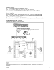
...)" (page 69). Power is supplied to "Stereo" (page 70). Using Multiple Microphones 161 Chapter 4: Connection with Optional Equipment VISCA OUT TERMINAL CAMERA EC-MIC(A7) 12 S VIDEO IN MIC(A1/A3) 1(R) 2(L) RGB IN RGB OUT (PLUG IN POWER)...microphone, see "Using the PCSA-A7 Microphones" on installation of the Audio setup menu, and set "Input Mode" to the microphones from the System. Using Multiple Microphones You can input the stereo sound from two PCS-A1 (supplied with the PCS-XG80) or PCSA-A3 microphone (not supplied) Microphone (Right) To use the connected microphones Set...
...)" (page 69). Power is supplied to "Stereo" (page 70). Using Multiple Microphones 161 Chapter 4: Connection with Optional Equipment VISCA OUT TERMINAL CAMERA EC-MIC(A7) 12 S VIDEO IN MIC(A1/A3) 1(R) 2(L) RGB IN RGB OUT (PLUG IN POWER)...microphone, see "Using the PCSA-A7 Microphones" on installation of the Audio setup menu, and set "Input Mode" to the microphones from the System. Using Multiple Microphones You can input the stereo sound from two PCS-A1 (supplied with the PCS-XG80) or PCSA-A3 microphone (not supplied) Microphone (Right) To use the connected microphones Set...
Operating Instructions
Page 188
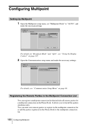
... 66. You can register a multipoint connection list that includes all the parties simultaneously. Registering the Remote Parties in the Multipoint Connection List You can enter new remote parties to register in the multipoint connection list or add the parties registered in the Phone Book. Configuring Multipoint Setting Up Multipoint 1 Open the Multipoint setup menu, set "Multipoint Mode" to "AUTO", and...
... 66. You can register a multipoint connection list that includes all the parties simultaneously. Registering the Remote Parties in the Multipoint Connection List You can enter new remote parties to register in the multipoint connection list or add the parties registered in the Phone Book. Configuring Multipoint Setting Up Multipoint 1 Open the Multipoint setup menu, set "Multipoint Mode" to "AUTO", and...

Operating Instructions
Page 190
... details on the Remote Commander. You can add the marks to register in the multipoint connection list. 2 Press the button on the setup, see step 3 in the multipoint connection list. Phone Book Default Group Room 101 ISDN 01-2345-6789 Cancel On Connect Edit Copy Delete The... (multipoint) mark is added to the lower right of Lines 28(128K) Save Cancel 5 Set up to make a multipoint connection. Enter all the parties to which you want to five parties using the same procedure as 190 Configuring...
... details on the Remote Commander. You can add the marks to register in the multipoint connection list. 2 Press the button on the setup, see step 3 in the multipoint connection list. Phone Book Default Group Room 101 ISDN 01-2345-6789 Cancel On Connect Edit Copy Delete The... (multipoint) mark is added to the lower right of Lines 28(128K) Save Cancel 5 Set up to make a multipoint connection. Enter all the parties to which you want to five parties using the same procedure as 190 Configuring...

Operating Instructions
Page 229
...User Name and Password are entered correctly. 195 Now obtaining an IP address via DHCP. 196 Configure the DNS address or use the IP address to dial. 201, 217 Call not responded. 218 Local number is correct. 207 The remote terminal may not be registered in the ISDN Setup menu. Line connected... connected with 1B (64K). 219 Local number setting for ISDN configuration is different. 236 Regarded as a secondary terminal as Far End Camera Control is set to Off. 237 Check the line interface or the IP address is set correctly in gatekeeper. Dial using IP address. 234 Dialing the same address ...
...User Name and Password are entered correctly. 195 Now obtaining an IP address via DHCP. 196 Configure the DNS address or use the IP address to dial. 201, 217 Call not responded. 218 Local number is correct. 207 The remote terminal may not be registered in the ISDN Setup menu. Line connected... connected with 1B (64K). 219 Local number setting for ISDN configuration is different. 236 Regarded as a secondary terminal as Far End Camera Control is set to Off. 237 Check the line interface or the IP address is set correctly in gatekeeper. Dial using IP address. 234 Dialing the same address ...

Operating Instructions
Page 255
... Delay Setting Audio Output Delay REC OUT Mode On, Off Off, On Default-100ms, Default-50ms, Default, Default+50ms, Default+100ms, Custom Default-100ms, Default-50ms, Default, Default+50ms, Default+100ms, Custom Stereo, Monaural 2ch Beep Sound Sound Effect Dial Tone Ringer Tone Large, Medium, Small, Off Large, Medium, Small, Off Large, Medium, Small, Off Large, Medium, Small, Off G Video Basic Setup (page...
... Delay Setting Audio Output Delay REC OUT Mode On, Off Off, On Default-100ms, Default-50ms, Default, Default+50ms, Default+100ms, Custom Default-100ms, Default-50ms, Default, Default+50ms, Default+100ms, Custom Stereo, Monaural 2ch Beep Sound Sound Effect Dial Tone Ringer Tone Large, Medium, Small, Off Large, Medium, Small, Off Large, Medium, Small, Off Large, Medium, Small, Off G Video Basic Setup (page...
Integration Guide
Page 6
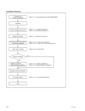
Optional software installation Operation test and confirmation Turn off the system End 1-2 PCS-XG80 Installation Flowchart Preparation at location of installation Unpacking Check of software . Updating of supplied accessories System connections Turn on the power to the system and perform initialization Other setup, if needed No Software installation Yes .
Optional software installation Operation test and confirmation Turn off the system End 1-2 PCS-XG80 Installation Flowchart Preparation at location of installation Unpacking Check of software . Updating of supplied accessories System connections Turn on the power to the system and perform initialization Other setup, if needed No Software installation Yes .
Integration Guide
Page 11
.... As a second camera, EVI-HD1, BRC-H700/Z700. (BRC-Z700 is supported by Ver. 2 and later.) Camera image flip Allows you should not set the "RF Remote Control Reception" as below. It is installed in a ceiling. For an explanation of the settings, refer to the following cameras. Supported cameras The PCS-XG80S can be connected to the operating instructions supplied with the unit. PCS-XG80 1-7
.... As a second camera, EVI-HD1, BRC-H700/Z700. (BRC-Z700 is supported by Ver. 2 and later.) Camera image flip Allows you should not set the "RF Remote Control Reception" as below. It is installed in a ceiling. For an explanation of the settings, refer to the following cameras. Supported cameras The PCS-XG80S can be connected to the operating instructions supplied with the unit. PCS-XG80 1-7
Integration Guide
Page 18
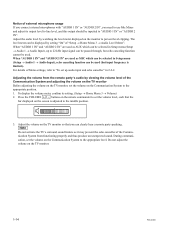
...PCS-XG80 The level meter can be used as AUX which can be passed through, but input frequency is adjusted to the middle position. 3. For details of Menu settings, refer to "To set the volume on the TV monitor, set up to 22 kHz input signal can clearly hear a remote... its setting. (Setup → Home Menu 3 → Volume) 2. Press the VOLUME [+]/[_] buttons on the remote commander to set the volume on the screen is limited.). Do not adjust the volume on the monitor to prevent level clipping. Notice of external microphone usage If you connect external microphones with ...
...PCS-XG80 The level meter can be used as AUX which can be passed through, but input frequency is adjusted to the middle position. 3. For details of Menu settings, refer to "To set the volume on the TV monitor, set up to 22 kHz input signal can clearly hear a remote... its setting. (Setup → Home Menu 3 → Volume) 2. Press the VOLUME [+]/[_] buttons on the remote commander to set the volume on the screen is limited.). Do not adjust the volume on the monitor to prevent level clipping. Notice of external microphone usage If you connect external microphones with ...
Integration Guide
Page 53
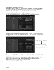
... the line level. The echo canceller is done by "Setup → Audio 1 → Audio Input". When AUDIO 1 IN is "On". PCS-XG80 2-7 In this signal does not go through a microphone mixer to "MIC". Menu setting is not enabled. Above shows that AUDIO 1 IN is "AUX", you cannot set "Setup → Audio 1 → Audio Input" to the AUDIO 1 IN...
... the line level. The echo canceller is done by "Setup → Audio 1 → Audio Input". When AUDIO 1 IN is "On". PCS-XG80 2-7 In this signal does not go through a microphone mixer to "MIC". Menu setting is not enabled. Above shows that AUDIO 1 IN is "AUX", you cannot set "Setup → Audio 1 → Audio Input" to the AUDIO 1 IN...

Integration Guide
Page 68
...PCS-XG80 "Communication mode" menu is displayed. The items below are shown both cameras. The descriptions under "(Encode)" show the setting status of the local system and those under "(Decode)" show the status of the receiving. Far End Terminal Name: Displays the terminal name of a remote party. Remote Address: Displays the address... encoding and video encoding formats used . Displays in this menu, depending on the status of a remote party. Audio Mode: Displays the current audio encoding format. Video Mode: Displays...
...PCS-XG80 "Communication mode" menu is displayed. The items below are shown both cameras. The descriptions under "(Encode)" show the setting status of the local system and those under "(Decode)" show the status of the receiving. Far End Terminal Name: Displays the terminal name of a remote party. Remote Address: Displays the address... encoding and video encoding formats used . Displays in this menu, depending on the status of a remote party. Audio Mode: Displays the current audio encoding format. Video Mode: Displays...


