Service Manual
Page 31
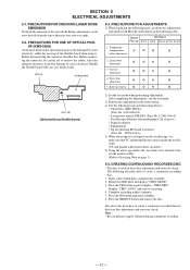
... the AMS knob and display "CREC MODE". 3. Complete recording within 5 minutes. 5. Press the §EJECT button and remove the disc. PRECAUTIONS FOR ADJUSTMENTS 1) When replacing the following tools and measuring devices. • Check Disc (MD) TDYS-1 (Parts No. 4-963-646-01) • Laser power meter LPM-8001 (Parts No. Temperature compensation G ¬ ¬...
... the AMS knob and display "CREC MODE". 3. Complete recording within 5 minutes. 5. Press the §EJECT button and remove the disc. PRECAUTIONS FOR ADJUSTMENTS 1) When replacing the following tools and measuring devices. • Check Disc (MD) TDYS-1 (Parts No. 4-963-646-01) • Laser power meter LPM-8001 (Parts No. Temperature compensation G ¬ ¬...

Service Manual
Page 33
...at intervals of adjustment to the specified value. Press the §EJECT button and remove the check disc (MD) TDYS-1. Note 1 : MO reading data will be erased during if a recorded disc is imposed. 11. Adjust the waveform so that the specified value is displayed. will be displayed. ...moment.) 10. Adjust the waveform so that the specified value is imposed automatically. 16. Press the §EJECT button and remove the disc. 14. Load the check disc (MD) TDYS-1. 15. Press the YES button and display "EFB = CD". Servo is satisfied as much as possible. (Write power traverse...
...at intervals of adjustment to the specified value. Press the §EJECT button and remove the check disc (MD) TDYS-1. Note 1 : MO reading data will be erased during if a recorded disc is imposed. 11. Adjust the waveform so that the specified value is displayed. will be displayed. ...moment.) 10. Adjust the waveform so that the specified value is imposed automatically. 16. Press the §EJECT button and remove the disc. 14. Load the check disc (MD) TDYS-1. 15. Press the YES button and display "EFB = CD". Servo is satisfied as much as possible. (Write power traverse...

Service Manual
Page 34
...MODE". 3. Rotate the AMS knob and display "CPLAY MODE". 3. Press the NO button, stop playback, press the §EJECT button, and remove the test disc. 5-9-2. tinuously Recorded Disc".). 2. Press the NO button when "C1 = AD = " is displayed. 5. Press the YES button and display " / c = ". Check that the... Method : 1. The display changes to "5-4. FOCUS BIAS CHECK Change the focus bias and check the focus tolerance amount. Load a check disc (MD) TDYS-1. 2. MO Error Rate Check Checking Method : 1. Creating Con- The first four digits indicate the C1 error rate, the two ...
...MODE". 3. Rotate the AMS knob and display "CPLAY MODE". 3. Press the NO button, stop playback, press the §EJECT button, and remove the test disc. 5-9-2. tinuously Recorded Disc".). 2. Press the NO button when "C1 = AD = " is displayed. 5. Press the YES button and display " / c = ". Check that the... Method : 1. The display changes to "5-4. FOCUS BIAS CHECK Change the focus bias and check the focus tolerance amount. Load a check disc (MD) TDYS-1. 2. MO Error Rate Check Checking Method : 1. Creating Con- The first four digits indicate the C1 error rate, the two ...
Service Manual
Page 37
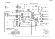
... SDA SCL LIMIT REFLECT PROTECT CHUCK IN PACK OUT PB P REC P LOAD-IN LOAD-OUT XRST - 37 - - 38 - M SLED+ SLED- TRK+ FSC+ FSC- M SPDL+ SPDL- MDS-JE700 6-2. BLOCK DIAGRAMS - HF MODULE SW IC103,Q102-104 SLED/SPINDLE MOTOR DRIVE FOCUS/TRACKING COIL DRIVE IC152 10 DRIVER 12 21 DRIVER 23 27 DRIVER...
... SDA SCL LIMIT REFLECT PROTECT CHUCK IN PACK OUT PB P REC P LOAD-IN LOAD-OUT XRST - 37 - - 38 - M SLED+ SLED- TRK+ FSC+ FSC- M SPDL+ SPDL- MDS-JE700 6-2. BLOCK DIAGRAMS - HF MODULE SW IC103,Q102-104 SLED/SPINDLE MOTOR DRIVE FOCUS/TRACKING COIL DRIVE IC152 10 DRIVER 12 21 DRIVER 23 27 DRIVER...
Service Manual
Page 38
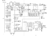
..., UK MAIN POWER S951 AC IN XOUT XIN XIN-T XOUT-T S. DOWN 27 28 25 24 09 X402 X401 12MHz 32.768KHz - 39 - - 40 - MAIN SECTION - MDS-JE700 -
..., UK MAIN POWER S951 AC IN XOUT XIN XIN-T XOUT-T S. DOWN 27 28 25 24 09 X402 X401 12MHz 32.768KHz - 39 - - 40 - MAIN SECTION - MDS-JE700 -
Service Manual
Page 74
MDS-JE700 9-960-804-11 Sony Corporation Home A&V Products Company - 88 - 97B0977-1 Printed in Japan © 1997. 2 Published by Service and Safety Engineering Dept. (Shibaura)
MDS-JE700 9-960-804-11 Sony Corporation Home A&V Products Company - 88 - 97B0977-1 Printed in Japan © 1997. 2 Published by Service and Safety Engineering Dept. (Shibaura)


