Sony MDS-JE700 - Mini Disc Player Support and Manuals
Get Help and Manuals for this Sony item
View All Support Options Below
Free Sony MDS-JE700 manuals!
Problems with Sony MDS-JE700?
Ask a Question
Free Sony MDS-JE700 manuals!
Problems with Sony MDS-JE700?
Ask a Question
Sony MDS-JE700 Videos

Sony MDS JE700
Duration: 2:28
Total Views: 165
Duration: 2:28
Total Views: 165
Popular Sony MDS-JE700 Manual Pages
Limited Warranty (US Only) - Page 1
... by Sony to state. REPAIR OR REPLACEMENT AS PROVIDED UNDER THIS WARRANTY IS THE EXCLUSIVE REMEDY OF THE CONSUMER. LABOR: For a period of one (1) year. ACCESSORIES: Parts and labor for all accessories are for product information or operation, call :
1-800-488-SONY (7669)
Printed in the United States. This warranty does not cover customer instruction, installation, set up...
Service Manual - Page 3
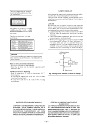
... LINE WITH MARK ! REPLACE THESE COMPONENTS WITH SONY PARTS WHOSE PART NUMBERS APPEAR AS SHOWN IN THIS MANUAL OR IN SUPPLEMENTS PUBLISHED BY SONY. LES COMPOSANTS IDENTIFIÉS PAR UNE MARQUE ! This appliance is located on Set
0.15µF
1.5kΩ
AC voltmeter (0.75V)
Earth Ground
Fig.
SAFETY CHECK-OUT
After correcting the original service problem, perform the following...
Service Manual - Page 5
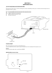
... : For measuring IOP (Check the deterioration of the optical pick-up laser) TEO : TRK error signal (Traverse adjustment) VC : Reference level for checking the waveform of the BD board. The... RESET.
[MAIN BOARD] (Conductor Side)
IC401
CN303
Short land TP (RESET)
- 5 - SECTION 1 SERVICING NOTE
JIG FOR CHECKING BD BOARD WAVEFORM
The special jig (J-2501-124-A) is useful for checking the signal RF...
Service Manual - Page 9
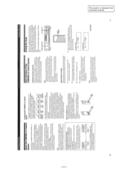
This section is extracted from instruction manual.
- 9 -
Service Manual - Page 28
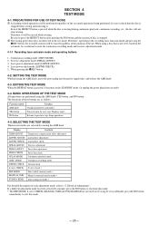
... the continuous recording mode and traverse adjustment mode.
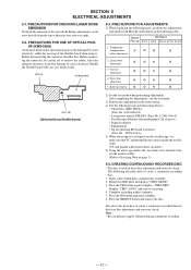
4-1-1.
If set accidentally, press the NO button
immediately to previous step. SECTION...Be sure to exit from an outlet.
4-4. Therefore, operating in servicing. When using the AMS knob, YES button, and NO button.... MODE DETRK CHECK S curve CHECK EEP MODE MANUAL CMD SVDATA READ
Contents Temperature compensation offset adjustment ...
Service Manual - Page 29
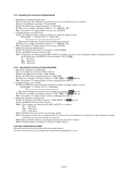
...error rates and ADER.
3. Note : The numbers " " displayed shows you error rates and ADER.
2. Note 3 : During the test mode, the erasing-protection tab will change the display as follows. If set... )". Entering the continuous playback mode
1 Set the disc in servicing.
"CPLAY MID" n "CPLAY OUT"n "CPLAY IN" 4
When pressed another time, the parts to be played back can be played ...
Service Manual - Page 30
...
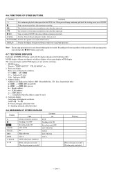
F= Focus auto gain collection value. FUNCTIONS OF OTHER BUTTONS
Function
Contents
¢
Sets continuous playback when pressed in the following order.
p
Stops continuous playback and continuous recording...REC button is displayed when the address cannot be read.
4. Error rate display
Error rates are displayed as follows.
Note : The erasing-protection tab ...servicing.
1.
Service Manual - Page 31
...bias adjustment and error rate check. Optical
BD Board
Pick-up flexible board
2) Set the test ...Press the YES button again to Servicing Note on the oscilloscope, etc.,
...parts, perform the adjustments
and checks with care as this may lose your eye-sight.
5-2. PRECAUTIONS FOR ADJUSTMENTS 1) When replacing the following tools and measuring devices.
• Check Disc (MD) TDYS-1 (Parts...
Service Manual - Page 37
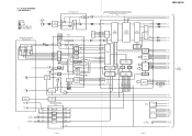
MDS-JE700
6-2.
HF MODULE SW
IC103,Q102-104
SLED/SPINDLE MOTOR DRIVE FOCUS/TRACKING COIL DRIVE
IC152
10 DRIVER
12 21
DRIVER 23 27
DRIVER 25 6
DRIVER...SIGNAL PROCESSOR EFM/ACIRC ENCODER/DECODER, SHOCK-PROOF MEMORY CONTROLLER,
ATRAC ENCODER/DECODER, 2M-BIT DRAM IC121
100 EFMO
15 14
...
D 7 8E 9F
IV AMP IV AMP
ABCD AMP
ABCD 35
FOCUS ERROR
FE 34
AMP
VC 31
VC
VC
E-F BALANCE
AT AMP
BPF
29...
Service Manual - Page 38
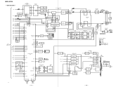
MDS-JE700
- DIN
DOUT ADDT DADT SCTX XINT
DIGITAL DATA SELECTOR
IC356
BUFFER IC355
7 1Y
IC0 6
12
IC1 4
10
DIGITAL OPTICAL OUT
1 IC352
AA BB
IC2
...
LOADING MOTOR DRIVE IC351
4
LOADING SW
Q351,352
94 LOAD OUT 39 LOAD V
FLCLK 71 FLDATA 72
FLCS 73
POWER DOWN 13
DISPLAY DRIVER IC730
62 SCK 63 SDATA 61 CS
60 RST
S1 4 S36 39
D1 40 D16 55
AC
FL730 FLUORESCENT
INDICATOR TUBE
SDA SCL
XRST...
Service Manual - Page 53
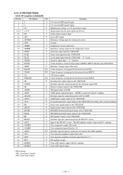
... setting pin for the internal circuit EQ Center frequency setting pin for the internal circuit BPF3T +3V power supply Center frequency setting pin for the internal circuit BPF22 Tracking error ... User comparator output (Not used) User comparator input (Fixed at "L") External capacitor pin for cutting the low band of the ADIP amplifier User operation amplifier output (Not used) User operation...
Service Manual - Page 62
... last of this parts list.
• Abbreviation CND : Canadian model
The components identified by mark ! Ne les remplacer que par une piéce portant le numéro spécifié.
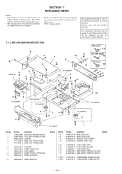
7-1. SECTION 7 EXPLODED VIEWS
NOTE: • Items marked "*" are not stocked since they are critical for routine service. sont critiques pour...
Service Manual - Page 66
... µ H
• Abbreviation CND : Canadian model
When indicating parts by mark ! No. *
Part No. Description
1-663-118-11 AC BOARD *********
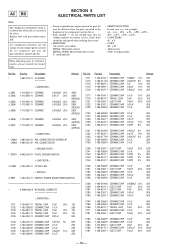
...replacements in the parts list may be anticipated when ordering these items.
• RESISTORS All resistors are in the diagrams or the components used on the set.
• Items marked "*" are not stocked since they are critical for routine service...
Service Manual - Page 72
...303-21 1-554-303-21 1-554-303-21 1-554-303-21 1-554-303-21
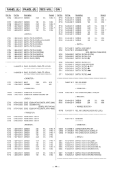
SWITCH, TACTILE (REPEAT) SWITCH, TACTILE (SCROLL/CLOCK SET) SWITCH, TACTILE (POWER) SWITCH, TACTILE (DISPLAY) SWITCH, TACTILE (CHAR)
S755 S756 S757 S758 S759
1-554-303-21 1-554-303-21...11 SWITCH, PUSH (1 KEY)(PB POSITION)
10K
5% 1/4W
S688 1-762-621-21 SWITCH, PUSH (1 KEY)(REC POSITION)
- 86 - Part No. Description
Remark Ref. No...
Service Manual - Page 74
MDS-JE700
9-960-804-11
Sony Corporation
Home A&V Products Company
- 88 -
97B0977-1 Printed in Japan © 1997. 2 Published by Service and Safety Engineering Dept. (Shibaura)
Sony MDS-JE700 Reviews
We have not received any reviews for Sony yet.