
Limited Warranty (US Only)
Page 1
... in exchange for defective parts for a period of protection, to any authorized Sony service facility. Proof of purchase in the form of a bill of sale or receipted invoice which vary from the Product. This warranty gives you specific legal rights, and you . 4-557-172-02 General Stereo/Hifi Components/Tape Decks ® CD Players/Mini Disc Players/Audio Systems Hifi Audio LIMITED WARRANTY Sony Electronics Inc. ("Sony") warrants this Product...
... in exchange for defective parts for a period of protection, to any authorized Sony service facility. Proof of purchase in the form of a bill of sale or receipted invoice which vary from the Product. This warranty gives you specific legal rights, and you . 4-557-172-02 General Stereo/Hifi Components/Tape Decks ® CD Players/Mini Disc Players/Audio Systems Hifi Audio LIMITED WARRANTY Sony Electronics Inc. ("Sony") warrants this Product...
Service Manual
Page 3
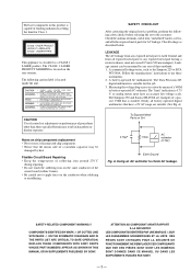
... set to the customer: Check the antenna terminals, metal trim, "metallized" knobs, screws, and all exposed metal parts to any exposed metal part having a return to chassis, must have a 2V AC range are examples of a passive VOM that the minus side of a VOM or battery-operated AC voltmeter. REPLACE THESE COMPONENTS WITH SONY PARTS WHOSE PART NUMBERS APPEAR AS SHOWN IN THIS MANUAL...
... set to the customer: Check the antenna terminals, metal trim, "metallized" knobs, screws, and all exposed metal parts to any exposed metal part having a return to chassis, must have a 2V AC range are examples of a passive VOM that the minus side of a VOM or battery-operated AC voltmeter. REPLACE THESE COMPONENTS WITH SONY PARTS WHOSE PART NUMBERS APPEAR AS SHOWN IN THIS MANUAL...
Service Manual
Page 5
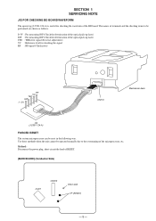
...deck Jig (J-2501-124-A) FORCED RESET The system microprocessor can be reset in the following way. Method : Disconnect the power plug, short-circuit the land of the microprocessor, etc. SECTION 1 SERVICING NOTE JIG FOR CHECKING BD BOARD WAVEFORM The special jig (J-2501-124-A) is useful for checking the signal RF : RF signal...deterioration of the optical pick-up laser) TEO : TRK error signal (Traverse adjustment) VC : Reference level for checking the waveform of the BD board. The names of terminals and the checking items to be operated normally due to the overrunning of RESET. [MAIN BOARD]...
...deck Jig (J-2501-124-A) FORCED RESET The system microprocessor can be reset in the following way. Method : Disconnect the power plug, short-circuit the land of the microprocessor, etc. SECTION 1 SERVICING NOTE JIG FOR CHECKING BD BOARD WAVEFORM The special jig (J-2501-124-A) is useful for checking the signal RF : RF signal...deterioration of the optical pick-up laser) TEO : TRK error signal (Traverse adjustment) VC : Reference level for checking the waveform of the BD board. The names of terminals and the checking items to be operated normally due to the overrunning of RESET. [MAIN BOARD]...

Service Manual
Page 6
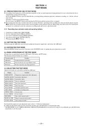
... faulty part of the unit. • The data amount stored in hexadecimal number. • The display of retries counted will start recording. 8. Turn OFF the power, and after a retry, "Retry Error" will be displayed on the music calendar will be performed smoothly. Press the EDIT/NO button several times to display the test mode (Fig. 1), and check the display. 9. Press the YES button to start blinking...
... faulty part of the unit. • The data amount stored in hexadecimal number. • The display of retries counted will start recording. 8. Turn OFF the power, and after a retry, "Retry Error" will be displayed on the music calendar will be performed smoothly. Press the EDIT/NO button several times to display the test mode (Fig. 1), and check the display. 9. Press the YES button to start blinking...

Service Manual
Page 8
Location of Parts and Controls SECTION 2 GENERAL 1 2345 6 7 89 0 !¡ 1 POWER switch 2 SCROLL/CLOCK SET button 3 CHAR button 4 CLEAR button 5 DISPLAY button 6 Disc compartment 7 § EJECT button 8 EDIT/NO button 9 YES button !º AMS knob !¡ REC LEVEL knob !™ INPUT switch !£ REC MODE swicth !ª !¢ r (recording) button !∞ p (stop) button !§ P (pause) button !¶ ( (play) button !• 0/) (fast backward/forward) buttons !ª Display window @º REPEAT button @¡ PROGRAM button @™ SHUFFLE button @£ CONTINUE ...
Location of Parts and Controls SECTION 2 GENERAL 1 2345 6 7 89 0 !¡ 1 POWER switch 2 SCROLL/CLOCK SET button 3 CHAR button 4 CLEAR button 5 DISPLAY button 6 Disc compartment 7 § EJECT button 8 EDIT/NO button 9 YES button !º AMS knob !¡ REC LEVEL knob !™ INPUT switch !£ REC MODE swicth !ª !¢ r (recording) button !∞ p (stop) button !§ P (pause) button !¶ ( (play) button !• 0/) (fast backward/forward) buttons !ª Display window @º REPEAT button @¡ PROGRAM button @™ SHUFFLE button @£ CONTINUE ...
Service Manual
Page 28
... be performed regardless of disc is stopped. 2 The erasing-protection tab is stopped before setting and removing it. Function name AMS knob YES button NO button Function Changes parameters and modes Proceeds onto the next step. Or unplug the power plug from this mode. - 28 - BASIC OPERATIONS OF THE TEST MODE All operations are not used in servicing. PRECAUTIONS FOR USE OF TEST MODE 1 As loading related operations will be careful not...
... be performed regardless of disc is stopped. 2 The erasing-protection tab is stopped before setting and removing it. Function name AMS knob YES button NO button Function Changes parameters and modes Proceeds onto the next step. Or unplug the power plug from this mode. - 28 - BASIC OPERATIONS OF THE TEST MODE All operations are not used in servicing. PRECAUTIONS FOR USE OF TEST MODE 1 As loading related operations will be careful not...
Service Manual
Page 29
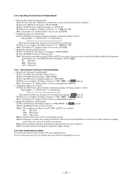
... pressed another time, the parts to be recorded can be erased is not used to be played back 1 Press the YES button during continuous recording, the display changes as follows. Operating the Continuous Recording Mode 1. Note 1 : The recording start addresses for playback only are as below . Therefore be careful not to set in servicing. Note : The numbers " " displayed show you error rates and ADER...
... pressed another time, the parts to be recorded can be erased is not used to be played back 1 Press the YES button during continuous recording, the display changes as follows. Operating the Continuous Recording Mode 1. Note 1 : The recording start addresses for playback only are as below . Therefore be careful not to set in servicing. Note : The numbers " " displayed show you error rates and ADER...
Service Manual
Page 30
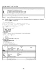
... Tracking auto gain failed - 30 - r REC Turns recording ON/OFF when pressed during continuous playback, the tracking servo turns ON/OFF. PLAY MODE Switches the spindle servo mode (CLVS and A). Stops operations. Error rate display Error rates are displayed as follows. SPACE Recording mode ON CLV LOCK Pit High reflection CLV-S ABCD adjustment completed Recording mode OFF CLV UNLOCK Groove Low reflection CLV-A A - MEANINGS OF OTHER DISPLAYS Display P Light...
... Tracking auto gain failed - 30 - r REC Turns recording ON/OFF when pressed during continuous playback, the tracking servo turns ON/OFF. PLAY MODE Switches the spindle servo mode (CLVS and A). Stops operations. Error rate display Error rates are displayed as follows. SPACE Recording mode ON CLV LOCK Pit High reflection CLV-S ABCD adjustment completed Recording mode OFF CLV UNLOCK Groove Low reflection CLV-A A - MEANINGS OF OTHER DISPLAYS Display P Light...
Service Manual
Page 31
... electricity. Insert a disc (blank disc) commercially available. 2. Press the §EJECT button and remove the disc. Before connecting the connector, be checked without the need to solder. (Refer to remove the solder. pick-up flexible board 2) Set the test mode when performing adjustments. Laser power ¬ ¬ G ¬ adjustment 3. Traverse ¬ ¬ G ¬ adjustment 4. Rotate the AMS knob and display "CREC MODE". 3. Complete recording...
... electricity. Insert a disc (blank disc) commercially available. 2. Press the §EJECT button and remove the disc. Before connecting the connector, be checked without the need to solder. (Refer to remove the solder. pick-up flexible board 2) Set the test mode when performing adjustments. Laser power ¬ ¬ G ¬ adjustment 3. Traverse ¬ ¬ G ¬ adjustment 4. Rotate the AMS knob and display "CREC MODE". 3. Complete recording...

Service Manual
Page 32
... YES button once and display "LD 0.9 mW $ ". 4. TEMPERATURE COMPENSATION OFFSET ADJUTMENT Save the temperature data at all times to stop the laser emission. (The NO button is turned on the objective lens of the optical pick-up .) Connect the digital volt meter to 0.91 mW. 9. When the NO button is the same as 25 ˚C reference data. Set the laser power...
... YES button once and display "LD 0.9 mW $ ". 4. TEMPERATURE COMPENSATION OFFSET ADJUTMENT Save the temperature data at all times to stop the laser emission. (The NO button is turned on the objective lens of the optical pick-up .) Connect the digital volt meter to 0.91 mW. 9. When the NO button is the same as 25 ˚C reference data. Set the laser power...

Service Manual
Page 33
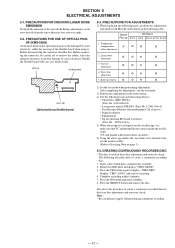
... displayed. Press the 0 button or ) button and move the optical pick- In this adjustment, waveform varies at intervals of approx. 2%. Adjust the waveform so that the specified value is satisfied as much as possible. (Traverse Waveform) A VC B Specification A = B 17. Adjust the waveform so that the specified value is satisfied as much as possible. (Read power traverse adjustment) (Traverse Waveform) A VC B Specification A = B 7. " changes...
... displayed. Press the 0 button or ) button and move the optical pick- In this adjustment, waveform varies at intervals of approx. 2%. Adjust the waveform so that the specified value is satisfied as much as possible. (Traverse Waveform) A VC B Specification A = B 17. Adjust the waveform so that the specified value is satisfied as much as possible. (Read power traverse adjustment) (Traverse Waveform) A VC B Specification A = B 7. " changes...
Service Manual
Page 37
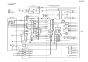
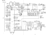
...MONITOR CONTROL MNT3 4 MNT2 3 MNT1 2 MNT0 1 SENS 9 CPU I CB J DA E VC PD ILCC LD 48 47 46 40 RF AMP IC101 RF AGC & EQ RF 38 1I 2J RF AMP BPF P-P AUX 33 PEAK & BOTTOM BOTM 36 PEAK 37 A 4 5B 6C D 7 8E 9F IV AMP IV AMP ABCD AMP ABCD 35 FOCUS ERROR FE 34 AMP VC 31 VC VC E-F BALANCE...BCK LRCK 512FS EEP ROM IC171 SDA 5 SCL 6 DETECT SW S681 - 683, S685 - 688 M903 LOADING MOTOR M LDON WRPWR MOD SDA SCL LIMIT REFLECT PROTECT CHUCK IN PACK OUT PB P REC P LOAD-IN LOAD-OUT XRST - 37 - - 38 - M SLED+ SLED- TRK+ FSC+ FSC- BLOCK DIAGRAMS - MDS-JE700 6-2.
...MONITOR CONTROL MNT3 4 MNT2 3 MNT1 2 MNT0 1 SENS 9 CPU I CB J DA E VC PD ILCC LD 48 47 46 40 RF AMP IC101 RF AGC & EQ RF 38 1I 2J RF AMP BPF P-P AUX 33 PEAK & BOTTOM BOTM 36 PEAK 37 A 4 5B 6C D 7 8E 9F IV AMP IV AMP ABCD AMP ABCD 35 FOCUS ERROR FE 34 AMP VC 31 VC VC E-F BALANCE...BCK LRCK 512FS EEP ROM IC171 SDA 5 SCL 6 DETECT SW S681 - 683, S685 - 688 M903 LOADING MOTOR M LDON WRPWR MOD SDA SCL LIMIT REFLECT PROTECT CHUCK IN PACK OUT PB P REC P LOAD-IN LOAD-OUT XRST - 37 - - 38 - M SLED+ SLED- TRK+ FSC+ FSC- BLOCK DIAGRAMS - MDS-JE700 6-2.
Service Manual
Page 38
...POWER S951 AC IN XOUT XIN XIN-T XOUT-T S. MDS-JE700 - DOWN 27 28 25 24 09 X402 X401 12MHz 32.768KHz - 39 - - 40 - DIN DOUT ADDT DADT SCTX XINT DIGITAL DATA SELECTOR IC356 BUFFER IC355 7 1Y IC0 6 12 IC1 4 10 DIGITAL OPTICAL OUT 1 IC352 AA BB IC2 5 8 14 2 13 3 IC353 DIGITAL OPTICAL IN1 11 3 IC354 DIGITAL OPTICAL IN2 J352 9 DIGITAL COAXIAL...97 PROTECT 6 CHUCK IN 8 PACK OUT 38 PLAY P 37 REC P KEY0 3 KEY1 4 KEY2 5 TIMER SW 9 SOURCE SW 10 JOG1 50 JOG0 51 FS32 54 FS44 55 FS48 56 SYSTEM CONTROL IC401 D351 AMP Q353 MATRIX SW LED DRIVE Q701 - 703 J350 CONTROL ...
...POWER S951 AC IN XOUT XIN XIN-T XOUT-T S. MDS-JE700 - DOWN 27 28 25 24 09 X402 X401 12MHz 32.768KHz - 39 - - 40 - DIN DOUT ADDT DADT SCTX XINT DIGITAL DATA SELECTOR IC356 BUFFER IC355 7 1Y IC0 6 12 IC1 4 10 DIGITAL OPTICAL OUT 1 IC352 AA BB IC2 5 8 14 2 13 3 IC353 DIGITAL OPTICAL IN1 11 3 IC354 DIGITAL OPTICAL IN2 J352 9 DIGITAL COAXIAL...97 PROTECT 6 CHUCK IN 8 PACK OUT 38 PLAY P 37 REC P KEY0 3 KEY1 4 KEY2 5 TIMER SW 9 SOURCE SW 10 JOG1 50 JOG0 51 FS32 54 FS44 55 FS48 56 SYSTEM CONTROL IC401 D351 AMP Q353 MATRIX SW LED DRIVE Q701 - 703 J350 CONTROL ...
Service Manual
Page 53
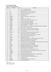
... capacitor connection pin for the RF AGC circuit Input to the RF AGC circuit The RF amplifier output is input with AC coupling User comparator output (Not used) User comparator input (Fixed at "L") External capacitor pin for cutting the low band of the ADIP amplifier User operation amplifier output (Not used) User operation amplifier inversion input (Fixed at "L") RF amplifier output Groove RF signal is input with AC coupling Groove RF signal output • Abbreviation APC: Auto Power Control AGC: Auto Gain Control - 67...
... capacitor connection pin for the RF AGC circuit Input to the RF AGC circuit The RF amplifier output is input with AC coupling User comparator output (Not used) User comparator input (Fixed at "L") External capacitor pin for cutting the low band of the ADIP amplifier User operation amplifier output (Not used) User operation amplifier inversion input (Fixed at "L") RF amplifier output Groove RF signal is input with AC coupling Groove RF signal output • Abbreviation APC: Auto Power Control AGC: Auto Gain Control - 67...

Service Manual
Page 54
... O CAS signal output for DRAM (Not used) O Address output for DRAM (Not used) 44 XRAS 45 XWE O RAS signal output for DRAM (Not used) O Write enable signal output for DRAM (Not used ) I System clock frequency setting "L": 45.1584 MHz, "H": 22.5792 MHz (Fixed at "H") 19 DVDD 20 DVSS - +3V power supply (Digital) - Ground (Digital) 21 DIN I Digital audio input (Optical input) 22 DOUT O Digital audio output (Optical output) 23 ADDT I Data input from the system control I System clock input (512Fs...
... O CAS signal output for DRAM (Not used) O Address output for DRAM (Not used) 44 XRAS 45 XWE O RAS signal output for DRAM (Not used) O Write enable signal output for DRAM (Not used ) I System clock frequency setting "L": 45.1584 MHz, "H": 22.5792 MHz (Fixed at "H") 19 DVDD 20 DVSS - +3V power supply (Digital) - Ground (Digital) 21 DIN I Digital audio input (Optical input) 22 DOUT O Digital audio output (Optical output) 23 ADDT I Data input from the system control I System clock input (512Fs...

Service Manual
Page 55
... power supply (Analog) I (A) A/D converter operational range upper limit voltage input (Fixed at "H") I (A) A/D converter operational range lower limit voltage input (Fixed at "L") O Playback EFM duplex signal output I (A) Playback EFM comparator slice level input - +3V power supply (Analog) I (A) Playback EFM comparator bias current input I (A) Playback EFM RF signal input - Ground (Analog) Phase comparison output for the clock playback analog PLL of the playback EFM O (3) (Not used) O (3) Phase comparison output for the recording/playback EFM master PLL I (A) Filter input...
... power supply (Analog) I (A) A/D converter operational range upper limit voltage input (Fixed at "H") I (A) A/D converter operational range lower limit voltage input (Fixed at "L") O Playback EFM duplex signal output I (A) Playback EFM comparator slice level input - +3V power supply (Analog) I (A) Playback EFM comparator bias current input I (A) Playback EFM RF signal input - Ground (Analog) Phase comparison output for the clock playback analog PLL of the playback EFM O (3) (Not used) O (3) Phase comparison output for the recording/playback EFM master PLL I (A) Filter input...

Service Manual
Page 56
... • Abbreviation EFM: Eight to TEST3 DVSS EFMO I/O Function O Tracking servo drive PWM output (+) - +3V power supply (Digital) O Focus servo drive PWM output (+) O Focus servo drive PWM output (-) O 176.4 kHz clock signal output (X'tal) (Not used) O Sled servo drive PWM output (-) O Sled servo drive PWM output (+) O Spindle servo drive PWM output (-) O Spindle servo drive PWM output (+) I (S) Test input (Fixed at "L") I - Pin No. 86 87 88 89...
... • Abbreviation EFM: Eight to TEST3 DVSS EFMO I/O Function O Tracking servo drive PWM output (+) - +3V power supply (Digital) O Focus servo drive PWM output (+) O Focus servo drive PWM output (-) O 176.4 kHz clock signal output (X'tal) (Not used) O Sled servo drive PWM output (-) O Sled servo drive PWM output (+) O Spindle servo drive PWM output (-) O Spindle servo drive PWM output (+) I (S) Test input (Fixed at "L") I - Pin No. 86 87 88 89...

Service Manual
Page 59
... I Track jump signal input from the recording position detection switch 38 PLAY I CONTROL A1 signal input 18 - 19 - Ground 27 XOUT O Main clock output (12 MHz) 28 XIN I BEEP sound output switching signal input (Not used O 20 SYSTEM-RST System reset signal input I For several hundreds msec after the power supply rises, "L" is output when test mode (Not used - 73 - Ground 30 (S1) 31 - O Not used ) 2 DAOUT 1 O Test pin. Pin Name I Test pin (Fixed at "L") 22...
... I Track jump signal input from the recording position detection switch 38 PLAY I CONTROL A1 signal input 18 - 19 - Ground 27 XOUT O Main clock output (12 MHz) 28 XIN I BEEP sound output switching signal input (Not used O 20 SYSTEM-RST System reset signal input I For several hundreds msec after the power supply rises, "L" is output when test mode (Not used - 73 - Ground 30 (S1) 31 - O Not used ) 2 DAOUT 1 O Test pin. Pin Name I Test pin (Fixed at "L") 22...

Service Manual
Page 60
... the DIGITAL INPUT LED "L": Light O I Terminal for the playback only disc or TOC area (Not used) FOK signal input from the serial bus I Not used O Serial clock signal output to the display driver O Serial data signal output to the display driver O Chip select signal output to the display driver I Not used O Laser ON/OFF control output "H": Laser ON I Pit/groove detection input "H" is input for switching the used model I I Not used O Audio bus/remote control switching signal output (Not used) I Not used O I Clock destination select pin (Fixed at "L") I Not used O Not used...
... the DIGITAL INPUT LED "L": Light O I Terminal for the playback only disc or TOC area (Not used) FOK signal input from the serial bus I Not used O Serial clock signal output to the display driver O Serial data signal output to the display driver O Chip select signal output to the display driver I Not used O Laser ON/OFF control output "H": Laser ON I Pit/groove detection input "H" is input for switching the used model I I Not used O Audio bus/remote control switching signal output (Not used) I Not used O I Clock destination select pin (Fixed at "L") I Not used O Not used...

Service Manual
Page 61
... PROTECT 98 REFLECT 99 GND 100 +3.3V I/O Function O Reset signal output to the CXD2650R and motor driver Reset: "L" O BEEP PWM output (Not used) O Reset signal output to the D/A, A/D converter Reset: "L" O Digital input selection signal output Laser modulation switching signal output Playback power: "L", stop: "H" Recording power: 0.5S O 2S O Not used O Writing data transmission timing output to the CXD2650R O Shared with the magnetic head ON/OFF output O Latch signal output to the serial bus O Not used I Not used O Line out muting output O Loading motor control output...
... PROTECT 98 REFLECT 99 GND 100 +3.3V I/O Function O Reset signal output to the CXD2650R and motor driver Reset: "L" O BEEP PWM output (Not used) O Reset signal output to the D/A, A/D converter Reset: "L" O Digital input selection signal output Laser modulation switching signal output Playback power: "L", stop: "H" Recording power: 0.5S O 2S O Not used O Writing data transmission timing output to the CXD2650R O Shared with the magnetic head ON/OFF output O Latch signal output to the serial bus O Not used I Not used O Line out muting output O Loading motor control output...


