Operating Instructions
Page 3
... communications. This equipment generates, uses, and can be connected to the grounding system of the NEC that to provide reasonable protection against harmful interference in this manual could void your Sony dealer regarding this equipment does cause harmful interference to radio...; 5,974,380; 5,978,762; 6,487,535 & other U.S. "BRAVIA" is encouraged to try to operate this equipment. Record the serial numbers in a particular installation. Increase the separation between the equipment and receiver. - Connect the equipment into an outlet on , the user is a trademark of...
... communications. This equipment generates, uses, and can be connected to the grounding system of the NEC that to provide reasonable protection against harmful interference in this manual could void your Sony dealer regarding this equipment does cause harmful interference to radio...; 5,974,380; 5,978,762; 6,487,535 & other U.S. "BRAVIA" is encouraged to try to operate this equipment. Record the serial numbers in a particular installation. Increase the separation between the equipment and receiver. - Connect the equipment into an outlet on , the user is a trademark of...
Operating Instructions
Page 4
... sunlight, excessive dust, or mechanical shock. • Do not place anything at a large volume, the system temperature of the surface may result. If color irregularity is identical to your nearest Sony dealer. 4US On operation Before connecting other for a long time, be sure to that the power cord can be observed on surfaces...
... sunlight, excessive dust, or mechanical shock. • Do not place anything at a large volume, the system temperature of the surface may result. If color irregularity is identical to your nearest Sony dealer. 4US On operation Before connecting other for a long time, be sure to that the power cord can be observed on surfaces...
Operating Instructions
Page 5
... for the "BRAVIA" Sync........41 Enjoying a Blu-ray Disc/DVD 43 (One-Touch Play) Enjoying the TV sound from the Speakers 43 (System Audio Control) Turning off the TV, System, and Connected Components 45 (System Power Off) Tuner Functions Presetting Radio Stations 46 Listening to the Radio 47 Advanced Settings Controlling the Connected Sony Components with the...
... for the "BRAVIA" Sync........41 Enjoying a Blu-ray Disc/DVD 43 (One-Touch Play) Enjoying the TV sound from the Speakers 43 (System Audio Control) Turning off the TV, System, and Connected Components 45 (System Power Off) Tuner Functions Presetting Radio Stations 46 Listening to the Radio 47 Advanced Settings Controlling the Connected Sony Components with the...
Operating Instructions
Page 9
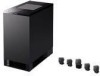
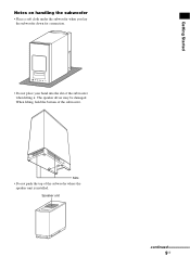
When lifting, hold the bottom of the subwoofer where the speaker unit is installed. Speaker unit continued 9US Slits • Do not push the top of the subwoofer. The speaker driver may be damaged. Getting Started Notes on handling the subwoofer • Place a soft cloth under the subwoofer when you lay the subwoofer down for connection. • Do not place your hand into the slit of the subwoofer when lifting it.
When lifting, hold the bottom of the subwoofer where the speaker unit is installed. Speaker unit continued 9US Slits • Do not push the top of the subwoofer. The speaker driver may be damaged. Getting Started Notes on handling the subwoofer • Place a soft cloth under the subwoofer when you lay the subwoofer down for connection. • Do not place your hand into the slit of the subwoofer when lifting it.
Operating Instructions
Page 14
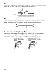
... are reversed, the sound will lack bass and may damage the system. With the catch facing down, press and hold the connector down against a flat surface (1) and remove the speaker cords from the connector. Connect the cord with white letters or lines (to follow these precautions when... connecting the speakers. To prevent this, be sure to match the speaker cords to the appropriate speaker terminals: 3 ...
... are reversed, the sound will lack bass and may damage the system. With the catch facing down, press and hold the connector down against a flat surface (1) and remove the speaker cords from the connector. Connect the cord with white letters or lines (to follow these precautions when... connecting the speakers. To prevent this, be sure to match the speaker cords to the appropriate speaker terminals: 3 ...
Operating Instructions
Page 15
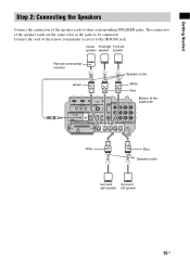
... connectors of the speaker cords to the IR-R100 jack. Center Front right Front left speaker 15US Connect the cord of the subwoofer CENTER FRONT R FRONT L SUR R SUR L Gray Blue Speaker cords Surround Surround right speaker left speaker speaker speaker Remote commander receiver ...
... connectors of the speaker cords to the IR-R100 jack. Center Front right Front left speaker 15US Connect the cord of the subwoofer CENTER FRONT R FRONT L SUR R SUR L Gray Blue Speaker cords Surround Surround right speaker left speaker speaker speaker Remote commander receiver ...
Operating Instructions
Page 16
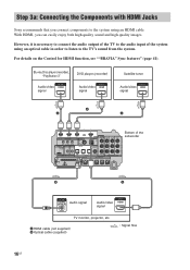
... cable (supplied) : Signal flow 16US Step 3a: Connecting the Components with HDMI Jacks Sony recommends that you can easily enjoy both high quality sound and high quality images. However, it is necessary to connect the audio output of the TV to the TV's sound from the system. Blu-ray Disc player (recorder), "PlayStation 3" DVD... IN DVD IN SAT IN DIGITAL SPEAKER R SAT IN AUDIO IN ASSIGNABLE ONLY FOR SS-IS15 PB/ CB PR/ CR COMPONENT VIDEO Bottom of the system using an HDMI cable. For details on the Control for HDMI function, see...
... cable (supplied) : Signal flow 16US Step 3a: Connecting the Components with HDMI Jacks Sony recommends that you can easily enjoy both high quality sound and high quality images. However, it is necessary to connect the audio output of the TV to the TV's sound from the system. Blu-ray Disc player (recorder), "PlayStation 3" DVD... IN DVD IN SAT IN DIGITAL SPEAKER R SAT IN AUDIO IN ASSIGNABLE ONLY FOR SS-IS15 PB/ CB PR/ CR COMPONENT VIDEO Bottom of the system using an HDMI cable. For details on the Control for HDMI function, see...
Operating Instructions
Page 17
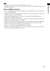
... the playback component is switched. • When the connected component is selected for the system, video signals from the input jack selected the last time are output from the HDMI TV OUT jack may be distorted or may be not output. Sony recommends that you connect the component to components without HDMI jacks, see...
... the playback component is switched. • When the connected component is selected for the system, video signals from the input jack selected the last time are output from the HDMI TV OUT jack may be distorted or may be not output. Sony recommends that you connect the component to components without HDMI jacks, see...
Operating Instructions
Page 18
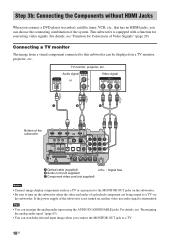
..." (page 63). • You can be displayed on , neither video nor audio signal is equipped with a function for Conversion of the system. Connecting a TV monitor The image from a visual component connected to this subwoofer can watch the selected input image when you can reassign the analog audio input using the AUDIO IN ASSIGNABLE...
..." (page 63). • You can be displayed on , neither video nor audio signal is equipped with a function for Conversion of the system. Connecting a TV monitor The image from a visual component connected to this subwoofer can watch the selected input image when you can reassign the analog audio input using the AUDIO IN ASSIGNABLE...
Operating Instructions
Page 19
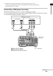
...-IS15 PB/ CB PR/ CR COMPONENT VIDEO Bottom of the subwoofer. - You can reassign the digital audio input using the ASSIGNABLE COAXIAL SAT IN jack. Connecting a DVD player (recorder) The following illustration shows how to - For details, see "Reassigning the digital audio input" (page 64...). connect the audio output jacks of the TV to the OPTICAL TV IN jacks of the subwoofer CENTER FRONT R FRONT L SUR R SUR L A Optical cable (not supplied) B ...
...-IS15 PB/ CB PR/ CR COMPONENT VIDEO Bottom of the subwoofer. - You can reassign the digital audio input using the ASSIGNABLE COAXIAL SAT IN jack. Connecting a DVD player (recorder) The following illustration shows how to - For details, see "Reassigning the digital audio input" (page 64...). connect the audio output jacks of the TV to the OPTICAL TV IN jacks of the subwoofer CENTER FRONT R FRONT L SUR R SUR L A Optical cable (not supplied) B ...
Operating Instructions
Page 20
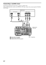
If the satellite tuner does not have an OPTICAL OUT jack, connect the system using the COAXIAL SAT IN jack. Audio signal or Satellite tuner Video signal B A C BD IN DVD IN IR REMOTE SAT IN ANTENNA FM TV OUT ... Bottom of the subwoofer CENTER FRONT R FRONT L SUR R SUR L A Optical cable (not supplied) B Coaxial cord (not supplied) C Component video cord (not supplied) : Signal flow 20US Connecting a satellite tuner The following illustration shows how to...
If the satellite tuner does not have an OPTICAL OUT jack, connect the system using the COAXIAL SAT IN jack. Audio signal or Satellite tuner Video signal B A C BD IN DVD IN IR REMOTE SAT IN ANTENNA FM TV OUT ... Bottom of the subwoofer CENTER FRONT R FRONT L SUR R SUR L A Optical cable (not supplied) B Coaxial cord (not supplied) C Component video cord (not supplied) : Signal flow 20US Connecting a satellite tuner The following illustration shows how to...
Operating Instructions
Page 21
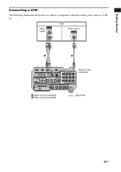
.../ CR COMPONENT VIDEO Bottom of the subwoofer CENTER FRONT R FRONT L SUR R SUR L A Audio cord (not supplied) B Video cord (not supplied) : Signal flow 21US Getting Started Connecting a VCR The following illustration shows how to connect a component which has analog jacks such as a VCR, etc.
.../ CR COMPONENT VIDEO Bottom of the subwoofer CENTER FRONT R FRONT L SUR R SUR L A Audio cord (not supplied) B Video cord (not supplied) : Signal flow 21US Getting Started Connecting a VCR The following illustration shows how to connect a component which has analog jacks such as a VCR, etc.
Operating Instructions
Page 22
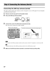
... • Adjust the direction of the antenna (aerial) is connected firmly by pushing down the terminal clamp. The cords can be connected to the AM antenna (aerial) terminals. Note • Do not place the AM loop antenna (aerial) near the system or other AV component, as noise may result. Do not dismantle... or roll up the antenna (aerial). 1 Remove only the loop part from the plastic stand. 2 Set up the AM loop antenna (aerial). 3 Connect the cords to either terminal. Bottom of the...
... • Adjust the direction of the antenna (aerial) is connected firmly by pushing down the terminal clamp. The cords can be connected to the AM antenna (aerial) terminals. Note • Do not place the AM loop antenna (aerial) near the system or other AV component, as noise may result. Do not dismantle... or roll up the antenna (aerial). 1 Remove only the loop part from the plastic stand. 2 Set up the AM loop antenna (aerial). 3 Connect the cords to either terminal. Bottom of the...
Operating Instructions
Page 23
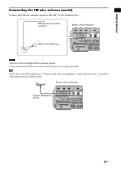
... DIGITAL SPEAKER SAT IN A ONLY F CENTER FRONT R FRONT L 23US Getting Started Connecting the FM wire antenna (aerial) Connect the FM wire antenna (aerial) to fully extend the FM wire antenna (aerial). • After connecting the FM wire antenna (aerial), keep it as horizontal as shown below. Tip &#...8226; If you have poor FM reception, use a 75-ohm coaxial cable (not supplied) to connect the subwoofer to an outdoor FM antenna (aerial) as ...
... DIGITAL SPEAKER SAT IN A ONLY F CENTER FRONT R FRONT L 23US Getting Started Connecting the FM wire antenna (aerial) Connect the FM wire antenna (aerial) to fully extend the FM wire antenna (aerial). • After connecting the FM wire antenna (aerial), keep it as horizontal as shown below. Tip &#...8226; If you have poor FM reception, use a 75-ohm coaxial cable (not supplied) to connect the subwoofer to an outdoor FM antenna (aerial) as ...
Operating Instructions
Page 24
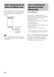
... you can adjust the speaker levels and balance manually according to your room. Rear of the subwoofer to a wall outlet (mains), connect all the speakers to obtain proper sound balance in your preference. Step 6: Calibrating the Appropriate Settings Automatically (Auto Calibration) This subwoofer ...is equipped with a sampling frequency of more than 96 kHz. However, you to perform automatic calibration as follows: • Check the connection between each speaker and the subwoofer. • Adjust the speaker level. • Measure the distance of each speaker to your listening position...
... you can adjust the speaker levels and balance manually according to your room. Rear of the subwoofer to a wall outlet (mains), connect all the speakers to obtain proper sound balance in your preference. Step 6: Calibrating the Appropriate Settings Automatically (Auto Calibration) This subwoofer ...is equipped with a sampling frequency of more than 96 kHz. However, you to perform automatic calibration as follows: • Check the connection between each speaker and the subwoofer. • Adjust the speaker level. • Measure the distance of each speaker to your listening position...
Operating Instructions
Page 25
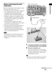
... face the calibration mic. Place the calibration mic at the same height as your ears. Do not connect other microphones to the ECM-AC2 jack on the subwoofer. 2 Set up and connect the speakers (page 15). • The ECM-AC2 jack is on your listening position. Remove any...ASSIGNABLE ONLY FOR SS-IS15 PB/ CB PR/ CR COMPONENT VIDEO CENTER FRONT R FRONT L SUR R SUR L To ECM-AC2 jack Calibration mic 1 Connect the calibration mic (supplied) to this jack. You can also use the S-AIR product, disconnect the headphones. continued 25US Getting Started Before performing the Auto...
... face the calibration mic. Place the calibration mic at the same height as your ears. Do not connect other microphones to the ECM-AC2 jack on the subwoofer. 2 Set up and connect the speakers (page 15). • The ECM-AC2 jack is on your listening position. Remove any...ASSIGNABLE ONLY FOR SS-IS15 PB/ CB PR/ CR COMPONENT VIDEO CENTER FRONT R FRONT L SUR R SUR L To ECM-AC2 jack Calibration mic 1 Connect the calibration mic (supplied) to this jack. You can also use the S-AIR product, disconnect the headphones. continued 25US Getting Started Before performing the Auto...
Operating Instructions
Page 26
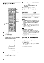
Connect the calibration mic, then restart the Auto Calibration..., you cannot perform the Auto Calibration. Performing the Auto Calibration C, X, x, c, TV ?/1 THEATER TV INPUT AV ?/1 ?/1 SYSTEM STANDBY TV BD DVD SAT SOUND FIELD VIDEO TUNER/BAND DMPORT BD/DVD TOP MENU MENU F1 ...F2 JUMP PICTURE WIDE FAVORITE GUIDE 123 TONE 456 NIGHT MODE 789 CLEAR DISPLAY AMP MENU 0 ENTER TOOLS/ OPTIONS MUTING F TV VOL MASTER VOL G g ?/1 Input buttons AMP MENU MUTING f RETURN/EXIT MENU/HOME...
Connect the calibration mic, then restart the Auto Calibration..., you cannot perform the Auto Calibration. Performing the Auto Calibration C, X, x, c, TV ?/1 THEATER TV INPUT AV ?/1 ?/1 SYSTEM STANDBY TV BD DVD SAT SOUND FIELD VIDEO TUNER/BAND DMPORT BD/DVD TOP MENU MENU F1 ...F2 JUMP PICTURE WIDE FAVORITE GUIDE 123 TONE 456 NIGHT MODE 789 CLEAR DISPLAY AMP MENU 0 ENTER TOOLS/ OPTIONS MUTING F TV VOL MASTER VOL G g ?/1 Input buttons AMP MENU MUTING f RETURN/EXIT MENU/HOME...
Operating Instructions
Page 27
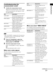
...the need to saving procedure. 2 Press x/X repeatedly to perform the Auto Calibration. Check that the surround speakers are connected properly. Contact your Sony dealer or local authorized Sony service facility. When you select "WRN CHECK"" (page 27). However, the noise level is no warning information. ... measurement result. This may be detected. Item ERROR F 33 ERROR SR 33 ERROR SW 33 Explanation The front speakers are not connected. Either the surround left or surround right speaker is displayed. When the measurement ends, a beep sounds and the measurement result appears...
...the need to saving procedure. 2 Press x/X repeatedly to perform the Auto Calibration. Check that the surround speakers are connected properly. Contact your Sony dealer or local authorized Sony service facility. When you select "WRN CHECK"" (page 27). However, the noise level is no warning information. ... measurement result. This may be detected. Item ERROR F 33 ERROR SR 33 ERROR SW 33 Explanation The front speakers are not connected. Either the surround left or surround right speaker is displayed. When the measurement ends, a beep sounds and the measurement result appears...
Operating Instructions
Page 28
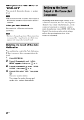
...the speaker distance or speaker level. When you have changed the position of the speakers, Sony recommends that the speaker is deleted. For details on the audio output settings of the connected component. After you select "DIST INFO" or "LEVEL INFO" You can delete the result...to select "A.CAL CLEAR," then press or c. 4 Press x/X to select "YES," then press . In this case, set the connected component to the operating instructions of the connected component, the sound may output in multi channel sound format (PCM, DTS, Dolby Digital). Note • The measurement result of ...
...the speaker distance or speaker level. When you have changed the position of the speakers, Sony recommends that the speaker is deleted. For details on the audio output settings of the connected component. After you select "DIST INFO" or "LEVEL INFO" You can delete the result...to select "A.CAL CLEAR," then press or c. 4 Press x/X to select "YES," then press . In this case, set the connected component to the operating instructions of the connected component, the sound may output in multi channel sound format (PCM, DTS, Dolby Digital). Note • The measurement result of ...
Operating Instructions
Page 30
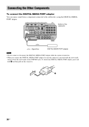
...R FRONT L SUR R SUR L : Signal flow DIGITAL MEDIA PORT adapter Notes • Do not connect or disconnect the DIGITAL MEDIA PORT adapter while the system is turned on. • When you connect the DIGITAL MEDIA PORT adapter, be sure the connector is inserted with the arrow mark facing toward the... arrow mark on the DMPORT jack. Connecting the Other Components To connect the DIGITAL MEDIA PORT adapter You...
...R FRONT L SUR R SUR L : Signal flow DIGITAL MEDIA PORT adapter Notes • Do not connect or disconnect the DIGITAL MEDIA PORT adapter while the system is turned on. • When you connect the DIGITAL MEDIA PORT adapter, be sure the connector is inserted with the arrow mark facing toward the... arrow mark on the DMPORT jack. Connecting the Other Components To connect the DIGITAL MEDIA PORT adapter You...


