
Operation Manual
Page 4
...Function Menu in this Manual 10 Chapter 4 Recording and Playback 4-1 Recording 33 4-1-1 Preparations for Recording 33 4-1-2 Recording Timecode and User Bit Values 34 4-1-3 Recording Procedure 36 4-2 Playback 37 4-2-1 Preparations for Playback 37 4-2-2 Playback Procedures 37 4-2-3 DMC (Dynamic Motion Control) Playback 40 Chapter 2 Location and Function of Parts 2-1 Control Panels 11 2-1-1 Upper Control Panel 12 2-1-2 Lower Control Panel 13 2-1-3 Switch Panel 22 2-2 Connector Panel 23 Chapter 3 Preparations 3-1 Connections to External Devices ......27 3-1-1 Connections to Digital...
...Function Menu in this Manual 10 Chapter 4 Recording and Playback 4-1 Recording 33 4-1-1 Preparations for Recording 33 4-1-2 Recording Timecode and User Bit Values 34 4-1-3 Recording Procedure 36 4-2 Playback 37 4-2-1 Preparations for Playback 37 4-2-2 Playback Procedures 37 4-2-3 DMC (Dynamic Motion Control) Playback 40 Chapter 2 Location and Function of Parts 2-1 Control Panels 11 2-1-1 Upper Control Panel 12 2-1-2 Lower Control Panel 13 2-1-3 Switch Panel 22 2-2 Connector Panel 23 Chapter 3 Preparations 3-1 Connections to External Devices ......27 3-1-1 Connections to Digital...

Operation Manual
Page 7
.... Cross fade editing In audio editing, you can change the function button definitions to be controlled with a varying playback speed memorized beforehand for a conventional analog VTR. Recording and playback levels can fade the audio track. Downconverter function The unit has an HD-to set separately from an external remote controller or editor through the parallel interface. In slow motion operation, the digital jog sound function provides the same ease of...
.... Cross fade editing In audio editing, you can change the function button definitions to be controlled with a varying playback speed memorized beforehand for a conventional analog VTR. Recording and playback levels can fade the audio track. Downconverter function The unit has an HD-to set separately from an external remote controller or editor through the parallel interface. In slow motion operation, the digital jog sound function provides the same ease of...

Operation Manual
Page 18
...-LTC R-RUN PARARUN 12 34 47 12 HD VTR control mode DF status TCG mode • Time data title This shows the type of time data which is being operated from the control panel (as a recorder) when two units are being used for editing. "P-CTRL": A device connected to the function display mode (see page 14). 18 2-1 Control Panels "HDV-LTC": The TCG synchronizes with the LTC...
...-LTC R-RUN PARARUN 12 34 47 12 HD VTR control mode DF status TCG mode • Time data title This shows the type of time data which is being operated from the control panel (as a recorder) when two units are being used for editing. "P-CTRL": A device connected to the function display mode (see page 14). 18 2-1 Control Panels "HDV-LTC": The TCG synchronizes with the LTC...

Operation Manual
Page 20
... time data display area. b PB (audio playback level control) knobs These individually adjust the output levels on . KEY INHI (inhibit) indicator This indicator lights when the KEY INHI switch on error messages, refer to the Maintenance Manual Volume 1. To return to protrude the control knobs and adjust the playback level while monitoring the audio level indication in audio level meter block 2. During playback, search, fast forward, or rewind, holding down the REC button allows you stop playback, the unit switches...
... time data display area. b PB (audio playback level control) knobs These individually adjust the output levels on . KEY INHI (inhibit) indicator This indicator lights when the KEY INHI switch on error messages, refer to the Maintenance Manual Volume 1. To return to protrude the control knobs and adjust the playback level while monitoring the audio level indication in audio level meter block 2. During playback, search, fast forward, or rewind, holding down the REC button allows you stop playback, the unit switches...
Operation Manual
Page 21
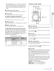
...) indicator and plays back in the forward direction. HDCAM: -1 to +2 times normal speed Digital Betacam: -1 to +3 times normal speed MPEG IMX: -1 to make the indicator flash by setting setup menu item 107. 7 Search control section 1 SHUTTLE button 2 JOG button 3 VAR button SHUTTLE REVERSE JOG VAR FORWAR 4 Search dial a SHUTTLE button To use the search dial for playback in variable speed mode, press this button, turning it on. For details of playback in shuttle mode, see the...
...) indicator and plays back in the forward direction. HDCAM: -1 to +2 times normal speed Digital Betacam: -1 to +3 times normal speed MPEG IMX: -1 to make the indicator flash by setting setup menu item 107. 7 Search control section 1 SHUTTLE button 2 JOG button 3 VAR button SHUTTLE REVERSE JOG VAR FORWAR 4 Search dial a SHUTTLE button To use the search dial for playback in variable speed mode, press this button, turning it on. For details of playback in shuttle mode, see the...
Operation Manual
Page 22
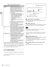
.../variable speed modes. 4 CONTROL PANEL connector KEY INHI ON OFF CONTROL PANEL 3 KEY INHI switch 2 "Memory Stick" slot 1 "Memory Stick" access indicator a "Memory Stick" access indicator Lights or flashes when data is ±1 time normal speed. Playback is possible. • HDCAM: Maximum 51 steps • Digital Betacam, MPEG IMX: Maximum 54 steps There are disabled in the lower control panel connection cable. 2-1-3 Switch Panel To access the switch panel, open the lower control...
.../variable speed modes. 4 CONTROL PANEL connector KEY INHI ON OFF CONTROL PANEL 3 KEY INHI switch 2 "Memory Stick" slot 1 "Memory Stick" access indicator a "Memory Stick" access indicator Lights or flashes when data is ±1 time normal speed. Playback is possible. • HDCAM: Maximum 51 steps • Digital Betacam, MPEG IMX: Maximum 54 steps There are disabled in the lower control panel connection cable. 2-1-3 Switch Panel To access the switch panel, open the lower control...
Operation Manual
Page 26
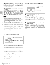
... audio signals whose output destination was set to "L" with the audio monitor signal selection buttons in the audio control section. b TIME CODE OUT connector (XLR 3-pin, male) This outputs a timecode according to the operating state of the unit, as follows: • During playback: the playback timecode By setting setup menu item 606, you can flow into this unit, possibly damaging the unit. • When connecting...
... audio signals whose output destination was set to "L" with the audio monitor signal selection buttons in the audio control section. b TIME CODE OUT connector (XLR 3-pin, male) This outputs a timecode according to the operating state of the unit, as follows: • During playback: the playback timecode By setting setup menu item 606, you can flow into this unit, possibly damaging the unit. • When connecting...

Operation Manual
Page 31
... Block B TAPE UNTHREAD Cassette is displayed for both the PARARUN mode and the standalone operation mode. STANDBY OFF Standby off mode T.RELEASE Tape tension release mode STOP Stop mode F.FWD Fast forward mode REW Rewind mode PREROLL Preroll mode PLAY Playback mode (servo unlocked) PLAY LOCK Playback mode (servo locked) PLAY Variation from Tape speed override mode normal speed (when "TSO" is selected in reverse direction SHUTTLE (Speed) Shuttle mode VAR (Speed) Variable speed mode AUTO EDIT Automatic editing mode PREVIEW Preview mode REVIEW Review mode 31...
... Block B TAPE UNTHREAD Cassette is displayed for both the PARARUN mode and the standalone operation mode. STANDBY OFF Standby off mode T.RELEASE Tape tension release mode STOP Stop mode F.FWD Fast forward mode REW Rewind mode PREROLL Preroll mode PLAY Playback mode (servo unlocked) PLAY LOCK Playback mode (servo locked) PLAY Variation from Tape speed override mode normal speed (when "TSO" is selected in reverse direction SHUTTLE (Speed) Shuttle mode VAR (Speed) Variable speed mode AUTO EDIT Automatic editing mode PREVIEW Preview mode REVIEW Review mode 31...

Operation Manual
Page 32
... how to remove the cassette in such a case, refer to the Installation Manual. 3-5-3 Preventing Accidental Erasure of Recordings To prevent a tape from the tape Press in one of the reels with a finger, and turn gently in the record inhibit plug. (ON) Return this plug to its original position to enable recording on the cassette. Large cassette STANDBY REW PLAY F FWD STOP Large cassette STANDBY button STOP button 1 Turn the POWER switch on . It...
... how to remove the cassette in such a case, refer to the Installation Manual. 3-5-3 Preventing Accidental Erasure of Recordings To prevent a tape from the tape Press in one of the reels with a finger, and turn gently in the record inhibit plug. (ON) Return this plug to its original position to enable recording on the cassette. Large cassette STANDBY REW PLAY F FWD STOP Large cassette STANDBY button STOP button 1 Turn the POWER switch on . It...

Operation Manual
Page 34
... audio level indication is close to simultaneously monitor the video and audio signals being recorded. It is automatically subjected to "TC". 2 Select F10 (TCG SET). To set F8 (COUNTER) to deemphasis processing. Using the emphasis-deemphasis processing improves the dynamic range by reducing high-frequency noise. 4-1-2 Recording Timecode and User Bit Values There are two ways of recording timecode, as follows. The function menu display changes...
... audio level indication is close to simultaneously monitor the video and audio signals being recorded. It is automatically subjected to "TC". 2 Select F10 (TCG SET). To set F8 (COUNTER) to deemphasis processing. Using the emphasis-deemphasis processing improves the dynamic range by reducing high-frequency noise. 4-1-2 Recording Timecode and User Bit Values There are two ways of recording timecode, as follows. The function menu display changes...

Operation Manual
Page 38
.... 38 4-2 Playback Chapter 4 Recording and Playback • Playback in shuttle mode Variable speed playback, with the speed determined by the angular position of the search dial • Playback in variable speed mode Variable speed playback, with another VTR. • DMC playback Playback at memorized varying speed. 1 1,2,3 Normal playback First insert a cassette. Cassette compartment STOP button PLAY button To start playback Press the PLAY button. The automatic rewind function can control the speed of rotating the search dial. To stop playback in setup menu item 125...
.... 38 4-2 Playback Chapter 4 Recording and Playback • Playback in shuttle mode Variable speed playback, with the speed determined by the angular position of the search dial • Playback in variable speed mode Variable speed playback, with another VTR. • DMC playback Playback at memorized varying speed. 1 1,2,3 Normal playback First insert a cassette. Cassette compartment STOP button PLAY button To start playback Press the PLAY button. The automatic rewind function can control the speed of rotating the search dial. To stop playback in setup menu item 125...

Operation Manual
Page 40
... starting DMC Stop playback Setting F3 (REVIEW) in function menu page P06: EDIT, turn the MULTI CONTROL knob to exit the tape speed override mode. On-air start point Preroll point Speed variation start and end points of highlights while recording, and then provide immediate DMC playback of character information displayed on again. Normal speed playback DMC playback Normal speed playback 40 4-2 Playback The SERVO indicator goes off. 2 When the adjustment is completed, release the PLAY button...
... starting DMC Stop playback Setting F3 (REVIEW) in function menu page P06: EDIT, turn the MULTI CONTROL knob to exit the tape speed override mode. On-air start point Preroll point Speed variation start and end points of highlights while recording, and then provide immediate DMC playback of character information displayed on again. Normal speed playback DMC playback Normal speed playback 40 4-2 Playback The SERVO indicator goes off. 2 When the adjustment is completed, release the PLAY button...

Operation Manual
Page 49
... makes the recorder forcibly enter the E-E mode, and the player video and audio signals are output to the OUT point, you can edit efficiently even if only one monitor is available, by using F6 (R/P SEL) in function menu page P06: EDIT on the recorder. The following procedure. 1 Connect the monitor to the recorder. 2 In the basic setup menu, set menu item 008 to "AUTO". 3 Select the player (PLAYER) using...
... makes the recorder forcibly enter the E-E mode, and the player video and audio signals are output to the OUT point, you can edit efficiently even if only one monitor is available, by using F6 (R/P SEL) in function menu page P06: EDIT on the recorder. The following procedure. 1 Connect the monitor to the recorder. 2 In the basic setup menu, set menu item 008 to "AUTO". 3 Select the player (PLAYER) using...

Operation Manual
Page 50
... tape. Chapter 5 Editing F1 (AUTOEDIT) F2 (PREVIEW) F3 (REVIEW) SHIFT/ENTRY button ALT/DELETE button To change the OUT point during automatic editing After starting the automatic editing, hold down the ALT/DELETE button and select F1 (AUTOEDIT) to recall the edit points. Note Audio, video, and CTL signals need to be recorded in advance in the audio and video when that you finish setting...
... tape. Chapter 5 Editing F1 (AUTOEDIT) F2 (PREVIEW) F3 (REVIEW) SHIFT/ENTRY button ALT/DELETE button To change the OUT point during automatic editing After starting the automatic editing, hold down the ALT/DELETE button and select F1 (AUTOEDIT) to recall the edit points. Note Audio, video, and CTL signals need to be recorded in advance in the audio and video when that you finish setting...
Operation Manual
Page 55
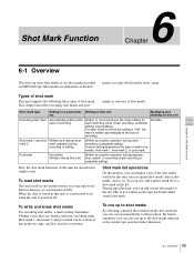
... marks or use shot marks recorded on a tape, and also erased or rewritten. For each mode for each time recording starts. Written by a manual shot mark 2 mark operation during crash recording or assemble editing. A menu setting determines the type of 200). By button operation, you can add virtual shot marks to the list. Post mark Not written (Written only by a button operation during playback, stop, search, or recording (crash recording or assemble...
... marks or use shot marks recorded on a tape, and also erased or rewritten. For each mode for each time recording starts. Written by a manual shot mark 2 mark operation during crash recording or assemble editing. A menu setting determines the type of 200). By button operation, you can add virtual shot marks to the list. Post mark Not written (Written only by a button operation during playback, stop, search, or recording (crash recording or assemble...

Operation Manual
Page 56
... a cassette tape loaded and F7 (LIST) selected, press the F FWD or REW button. Chapter 6 Shot Mark Function 56 6-2 Shot Mark Operations SHOT MRK REC/ERS REC REC SHOT MRK MARK LIST 190 shot marks have been read in setup menu item 631 "REC START MARK MODE" is set to "ON" (to write a recording start mark for 20 frames from the start recording in crash recording or assemble editing 1 Holding down...
... a cassette tape loaded and F7 (LIST) selected, press the F FWD or REW button. Chapter 6 Shot Mark Function 56 6-2 Shot Mark Operations SHOT MRK REC/ERS REC REC SHOT MRK MARK LIST 190 shot marks have been read in setup menu item 631 "REC START MARK MODE" is set to "ON" (to write a recording start mark for 20 frames from the start recording in crash recording or assemble editing 1 Holding down...
Operation Manual
Page 61
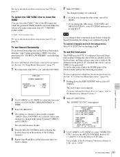
... "8-1-2 Function Menu Operations" (page 64). 1 Holding down the SHIFT/ENTRY button, select F9 (MENU). To select the SDI VANC line to 7. Make this selection by using setup menu item 653 "UMID HD VANC LINE". 1) VANC: Vertical ancillary (data) For more information about setup menu item 653, see Section "9-2 Setup Menu Operations" (page 75). 1 Set setup menu item 029 to the Maintenance Manual Volume 1. 2 Select F5 (SETTING). EFGH - To cancel changes and...
... "8-1-2 Function Menu Operations" (page 64). 1 Holding down the SHIFT/ENTRY button, select F9 (MENU). To select the SDI VANC line to 7. Make this selection by using setup menu item 653 "UMID HD VANC LINE". 1) VANC: Vertical ancillary (data) For more information about setup menu item 653, see Section "9-2 Setup Menu Operations" (page 75). 1 Set setup menu item 029 to the Maintenance Manual Volume 1. 2 Select F5 (SETTING). EFGH - To cancel changes and...

Operation Manual
Page 66
... by control from the device connected to the REMOTE1-IN (9P) connector. F2 (TCG MODE) Select one of timecode generated by the internal timecode generator, as calculated from a count of the playback tape. The LUB or VIUB time data type indicator lights, depending on the setting of the following running time of the tape being played back or recorded, as specified by control panel operation...
... by control from the device connected to the REMOTE1-IN (9P) connector. F2 (TCG MODE) Select one of timecode generated by the internal timecode generator, as calculated from a count of the playback tape. The LUB or VIUB time data type indicator lights, depending on the setting of the following running time of the tape being played back or recorded, as specified by control panel operation...
Operation Manual
Page 71
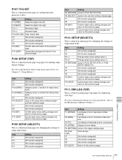
... Setting F1 (ERROR) List display of error description (initial setting) F2 (DATE) List display of error occurrence date and time F3 (TC) List display of timecode at error occurrence F4 (DETAIL) Display of setup menu items. Item Setting F1 (No function assigned) F2 (No function assigned) F3 (-) Change setup menu setting value (-). F3 (-) Decrement data. For more information about setup menu operations, see Chapter 9 "Setup Menus". P109: SETUP (SELECT1) This is a function menu page for changing the settings of error details F5 (SETTING...
... Setting F1 (ERROR) List display of error description (initial setting) F2 (DATE) List display of error occurrence date and time F3 (TC) List display of timecode at error occurrence F4 (DETAIL) Display of setup menu items. Item Setting F1 (No function assigned) F2 (No function assigned) F3 (-) Change setup menu setting value (-). F3 (-) Decrement data. For more information about setup menu operations, see Chapter 9 "Setup Menus". P109: SETUP (SELECT1) This is a function menu page for changing the settings of error details F5 (SETTING...
Operation Manual
Page 77
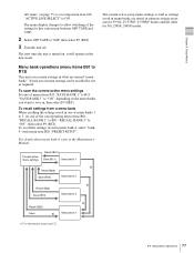
... OFF TAPE and 720P. 2 Select OFF TAPE or 720P, then select F9 (SET). 3 Turn the unit off. The menu display changes to allow switching of the corresponding menu items B01 "RECALL BANK 1" to B03 "RECALL BANK 3" to the Maintenance Manual. Current active menu settings Recall (B01) Save (B11) Menu bank 1 a) Recall (B02) Save (B12) Menu bank 2 Recall (B03) Save (B13) a) Menu bank 3 Recall (B20) Save a) a) Menu bank 4 a) Use maintenance menu item 122. 77 9-2 Setup Menu Operations
... OFF TAPE and 720P. 2 Select OFF TAPE or 720P, then select F9 (SET). 3 Turn the unit off. The menu display changes to allow switching of the corresponding menu items B01 "RECALL BANK 1" to B03 "RECALL BANK 3" to the Maintenance Manual. Current active menu settings Recall (B01) Save (B11) Menu bank 1 a) Recall (B02) Save (B12) Menu bank 2 Recall (B03) Save (B13) a) Menu bank 3 Recall (B20) Save a) a) Menu bank 4 a) Use maintenance menu item 122. 77 9-2 Setup Menu Operations


