
Operation Manual
Page 2
...following Electromagnetic Environment(s): E1 (residential), E2 (commercial and light industrial), E3 (urban outdoors), E4 (controlled EMC environment, ex. All interface cables used in order to comply with the limits for help. For the customers in the following measures: - studio de télévision). 2 ... à la pluie ou à l'humidité. This equipment has been tested and found to comply with the limits for use in Europe This product with the CE marking complies with the instructions, may cause harmful interference to qualified personnel only. Reorient or ...
...following Electromagnetic Environment(s): E1 (residential), E2 (commercial and light industrial), E3 (urban outdoors), E4 (controlled EMC environment, ex. All interface cables used in order to comply with the limits for help. For the customers in the following measures: - studio de télévision). 2 ... à la pluie ou à l'humidité. This equipment has been tested and found to comply with the limits for use in Europe This product with the CE marking complies with the instructions, may cause harmful interference to qualified personnel only. Reorient or ...
Operation Manual
Page 4
... Contents Setting the Frame Frequency 9 Chapter 1 Overview 1-1 Features 11 1-1-1 Camera Features 11 1-1-2 VTR Features 12 1-1-3 Other Features 12 1-2 Example of System Configuration 14 1-3 Precautions 15 1-4 Using the CD-ROM Manual 15 1-4-1 Preparations 15 1-4-2 Reading the CD-ROM Manual 15 Chapter 2 Locations and Functions of Parts and Controls 2-1 Power Supply 17 2-2 Accessory...
... Contents Setting the Frame Frequency 9 Chapter 1 Overview 1-1 Features 11 1-1-1 Camera Features 11 1-1-2 VTR Features 12 1-1-3 Other Features 12 1-2 Example of System Configuration 14 1-3 Precautions 15 1-4 Using the CD-ROM Manual 15 1-4-1 Preparations 15 1-4-2 Reading the CD-ROM Manual 15 Chapter 2 Locations and Functions of Parts and Controls 2-1 Power Supply 17 2-2 Accessory...

Operation Manual
Page 6
... Setting.. 95 5-3-5 Assigning Functions to Assignable Switches 96 5-3-6 Setting the Date/Time of the Internal Clock 98 5-3-7 Selecting a Lens File 99 5-3-8 Using UMID Data 100 5-3-9 Using the Hyper Gamma 102 5-3-10 Using the USER Gamma 103 5-4 Resetting USER Menu Settings to Assignable Switches. 80 5-2 Status Display on the Color Bars..88 5-2-8 Setting the...
... Setting.. 95 5-3-5 Assigning Functions to Assignable Switches 96 5-3-6 Setting the Date/Time of the Internal Clock 98 5-3-7 Selecting a Lens File 99 5-3-8 Using UMID Data 100 5-3-9 Using the Hyper Gamma 102 5-3-10 Using the USER Gamma 103 5-4 Resetting USER Menu Settings to Assignable Switches. 80 5-2 Status Display on the Color Bars..88 5-2-8 Setting the...

Operation Manual
Page 7
...Memory Stick 109 6-2 Saving and Loading Scene Files 110 6-2-1 Saving a Scene File 110 6-2-2 Loading a Scene File 112 6-2-3 Resetting the Camcorder Settings to the Standard Settings Saved in the Reference File 113 6-3 Jumping to a File-Related Menu Page When Inserting a "Memory Stick... 114 Chapter 7 Setting Up the Camcorder 7-1 Power Supply 116 7-1-1 Using a Battery Pack 116 7-1-2 Avoiding Breaks in Operation Due to an Exhausted Battery 116 7-1-3 Using an AC Adaptor 117 7-1-4 Using the Anton Bauer Ultralight System 117 7-2 Adjusting the Viewfinder 117 ...
...Memory Stick 109 6-2 Saving and Loading Scene Files 110 6-2-1 Saving a Scene File 110 6-2-2 Loading a Scene File 112 6-2-3 Resetting the Camcorder Settings to the Standard Settings Saved in the Reference File 113 6-3 Jumping to a File-Related Menu Page When Inserting a "Memory Stick... 114 Chapter 7 Setting Up the Camcorder 7-1 Power Supply 116 7-1-1 Using a Battery Pack 116 7-1-2 Avoiding Breaks in Operation Due to an Exhausted Battery 116 7-1-3 Using an AC Adaptor 117 7-1-4 Using the Anton Bauer Ultralight System 117 7-2 Adjusting the Viewfinder 117 ...

Operation Manual
Page 9
... 6 Confirm the b mark is positioned at the top left of the frame frequency first. To use the camcorder with a format other than the 23.98PsF format, you can switch pages by turning the MENU ... the MENU ON/ OFF switch to MAINTENANCE, then push the MENU knob. When the MAINTENANCE menu is used the MAINTENANCE menu before, the page that was on the screen when the last menu operation ended appears... MENU knob to move the b mark to ON while pushing the MENU knob. When any page of the camcorder is 23.98PsF. When a question mark appears at NEXT, then push the MENU knob. 3 Turn the MENU...
... 6 Confirm the b mark is positioned at the top left of the frame frequency first. To use the camcorder with a format other than the 23.98PsF format, you can switch pages by turning the MENU ... the MENU ON/ OFF switch to MAINTENANCE, then push the MENU knob. When the MAINTENANCE menu is used the MAINTENANCE menu before, the page that was on the screen when the last menu operation ended appears... MENU knob to move the b mark to ON while pushing the MENU knob. When any page of the camcorder is 23.98PsF. When a question mark appears at NEXT, then push the MENU knob. 3 Turn the MENU...

Operation Manual
Page 11
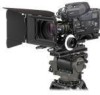
... Enhanced Vertical Definition System Shooting functions to cope with different shooting conditions • The multiple formats allow you to use the camcorder with various applications regardless of shooting format. • With the scene file function, you can easily recall sets of...Sony Corporation. Attaching an optional HKDW-902R extension board which puts this HD camcorder at the top of its class. The camcorder is compatible with 2,000,000 picture elements and an HDCAM format recorder combined integrally. Chapter 1 Overview Overview Chapter 1-1 Features The HDW-F900R camcorder...
... Enhanced Vertical Definition System Shooting functions to cope with different shooting conditions • The multiple formats allow you to use the camcorder with various applications regardless of shooting format. • With the scene file function, you can easily recall sets of...Sony Corporation. Attaching an optional HKDW-902R extension board which puts this HD camcorder at the top of its class. The camcorder is compatible with 2,000,000 picture elements and an HDCAM format recorder combined integrally. Chapter 1 Overview Overview Chapter 1-1 Features The HDW-F900R camcorder...

Operation Manual
Page 12
... an optional RM-B150/B750 or similar remote control unit, you can control the camera settings of the camcorder externally. 1-1-2 VTR Features HDCAM format • Use of the HDCAM format allows high performance HD digital recording and playback while preserving the same ease of cassette... displayed in the board's memory. When you pressed the button is used. This is very helpful for management of use as conventional camcorder equipment. • The same cassette size (S size) as Digital Betacam can be used to achieve the following long recording times. The automatic power shut-off...
... an optional RM-B150/B750 or similar remote control unit, you can control the camera settings of the camcorder externally. 1-1-2 VTR Features HDCAM format • Use of the HDCAM format allows high performance HD digital recording and playback while preserving the same ease of cassette... displayed in the board's memory. When you pressed the button is used. This is very helpful for management of use as conventional camcorder equipment. • The same cassette size (S size) as Digital Betacam can be used to achieve the following long recording times. The automatic power shut-off...

Operation Manual
Page 13
...and Image Inverter Board 13 Features Function extension interface and optional boards An extension connector can be attached to connect the supplied stereo microphone. Use of any tools. You can record either stereo or monaural sound. • An optional slot-in UHF portable tuner, WRR-855A/ ...; Four channels of 20-bit digital audio can be recorded. • The AUDIO OUT connector (XLR 5-pin) allows the camcorder to ensure proper balance) without the use of the following optional boards permits you to adjust the front-to-rear direction position (to output signals as stereo audio.
...and Image Inverter Board 13 Features Function extension interface and optional boards An extension connector can be attached to connect the supplied stereo microphone. Use of any tools. You can record either stereo or monaural sound. • An optional slot-in UHF portable tuner, WRR-855A/ ...; Four channels of 20-bit digital audio can be recorded. • The AUDIO OUT connector (XLR 5-pin) allows the camcorder to ensure proper balance) without the use of the following optional boards permits you to adjust the front-to-rear direction position (to output signals as stereo audio.

Operation Manual
Page 14
... Video monitor for color image check during shooting Audio output Audio equipment for monitoring (XLR 5-pin connector) 14 Example of the camcorder for the connected equipment. Chapter 1 Overview 1-2 Example of System Configuration The diagram below shows a typical configuration of System Configuration...-0.8 D Lens assembly -3.6 D to +0.4 D Lens assembly -2.4 D to operate the unit. In this manual, an optional HDVF-20A HD Electronic Viewfinder is used to instruct how to +0.5 D (3 × magnification) Part No. 1-547-341-11 A-8262-537-A A-8262-538-A A-8267-737-A A-8314-798-A BKW...
... Video monitor for color image check during shooting Audio output Audio equipment for monitoring (XLR 5-pin connector) 14 Example of the camcorder for the connected equipment. Chapter 1 Overview 1-2 Example of System Configuration The diagram below shows a typical configuration of System Configuration...-0.8 D Lens assembly -3.6 D to +0.4 D Lens assembly -2.4 D to operate the unit. In this manual, an optional HDVF-20A HD Electronic Viewfinder is used to instruct how to +0.5 D (3 × magnification) Part No. 1-547-341-11 A-8262-537-A A-8262-538-A A-8267-737-A A-8314-798-A BKW...

Operation Manual
Page 15
... version you shoot a scene that the portable communications devices near this unit be powered off the power. Chapter 1 Overview 1-3 Precautions Use and Storage Do not subject the unit to severe shocks The internal mechanism may not be displayed properly, depending on the version of Adobe...operation manual (English version). Contact your Sony service representative. • You can purchase a new one to replace it from the following URL: http://www.adobe.com/ Adobe and Adobe Reader are trademarks of the Operation Manual for the HDW-F900R in English and Japanese in PDF format....
... version you shoot a scene that the portable communications devices near this unit be powered off the power. Chapter 1 Overview 1-3 Precautions Use and Storage Do not subject the unit to severe shocks The internal mechanism may not be displayed properly, depending on the version of Adobe...operation manual (English version). Contact your Sony service representative. • You can purchase a new one to replace it from the following URL: http://www.adobe.com/ Adobe and Adobe Reader are trademarks of the Operation Manual for the HDW-F900R in English and Japanese in PDF format....

Operation Manual
Page 16
Part No. 3-991-858-0X Models covered HDW-F900R Chapter 1 Overview 16 Using the CD-ROM Manual When ordering, be sure to specify the part number of the manual you want.
Part No. 3-991-858-0X Models covered HDW-F900R Chapter 1 Overview 16 Using the CD-ROM Manual When ordering, be sure to specify the part number of the manual you want.

Operation Manual
Page 17
When using the auto interval recording mode, the video light is in the on position, putting the camcorder in recording mode turns the video light on automatically. Locations and Functions of Parts and Controls Chapter 2-1 Power Supply Chapter 2 Locations and Functions of Parts...a battery pack, BP-GL65, BP-GL95, or BP-L60S. b DC IN connector (XLR type, 4-pin, male) To operate the camcorder using its DC output cable to the LIGHT connector is not being used, attach the supplied XLR connector cover onto it. c POWER switch Turns the main power supply on immediately before recording starts...
When using the auto interval recording mode, the video light is in the on position, putting the camcorder in recording mode turns the video light on automatically. Locations and Functions of Parts and Controls Chapter 2-1 Power Supply Chapter 2 Locations and Functions of Parts...a battery pack, BP-GL65, BP-GL95, or BP-L60S. b DC IN connector (XLR type, 4-pin, male) To operate the camcorder using its DC output cable to the LIGHT connector is not being used, attach the supplied XLR connector cover onto it. c POWER switch Turns the main power supply on immediately before recording starts...

Operation Manual
Page 18
... W. g LENS connector (12-pin) Fit the lens cable to this to these posts. Do this shoe. d Lens mount (special bayonet mount) Use this cap fitted for mounting the lens. 2-2 Accessory Attachments a Shoulder strap posts b Light shoe Chapter 2 Locations and Functions of Parts and Controls i...cap g LENS connector a Shoulder strap posts Attach the supplied shoulder strap to ensure the best balance when shooting with the camcorder on your Sony representative for more information about the lenses you can move the shoulder pad forwards or backwards by raising up the lens mounting...
... W. g LENS connector (12-pin) Fit the lens cable to this to these posts. Do this shoe. d Lens mount (special bayonet mount) Use this cap fitted for mounting the lens. 2-2 Accessory Attachments a Shoulder strap posts b Light shoe Chapter 2 Locations and Functions of Parts and Controls i...cap g LENS connector a Shoulder strap posts Attach the supplied shoulder strap to ensure the best balance when shooting with the camcorder on your Sony representative for more information about the lenses you can move the shoulder pad forwards or backwards by raising up the lens mounting...

Operation Manual
Page 19
...h Built-in speaker Chapter 2 Locations and Functions of audio channels selected with the MONITOR switch. A microphone other than the supplied one may also be used to the earphone or speaker, depending on the setting of the CH-1/2 / CH-3/ 4 switch. 19 Audio Functions e MONITOR switch and CH-1/2 /... AUDIO OUT connector and EARPHONE jacks and the audio level meter in speaker. For details, see "5-3-5 Assigning Functions to the camcorder are output after passing through the earphone. Assigning the F.MIC MONO/STEREO function to the MIC IN connector between stereo and monaural sound....
...h Built-in speaker Chapter 2 Locations and Functions of audio channels selected with the MONITOR switch. A microphone other than the supplied one may also be used to the earphone or speaker, depending on the setting of the CH-1/2 / CH-3/ 4 switch. 19 Audio Functions e MONITOR switch and CH-1/2 /... AUDIO OUT connector and EARPHONE jacks and the audio level meter in speaker. For details, see "5-3-5 Assigning Functions to the camcorder are output after passing through the earphone. Assigning the F.MIC MONO/STEREO function to the MIC IN connector between stereo and monaural sound....

Operation Manual
Page 20
... sounds other than the alarm sound. MANUAL: Select this setting for each of audio channels 1 and 2. Minimum Maximum h Built-in speaker The speaker can be used to MANUAL. If you connect an earphone to reinforce visual warnings. The speaker also sounds alarms to the EARPHONE jack, the speaker is automatically muted...
... sounds other than the alarm sound. MANUAL: Select this setting for each of audio channels 1 and 2. Minimum Maximum h Built-in speaker The speaker can be used to MANUAL. If you connect an earphone to reinforce visual warnings. The speaker also sounds alarms to the EARPHONE jack, the speaker is automatically muted...

Operation Manual
Page 21
...UHF Portable Tuner. CH-3/CH-4 switches Select the audio input signals to be recorded on audio channels 3 and 4. F (front): The input signal source is used for channel-1 and -2 inputs, and the CH2 connector, for the microphones to be damaged. CH-1: Signal selected by the AUDIO IN CH-1 switch MIX:... input) connectors (XLR type, 3-pin, female) These are the same. R (rear): The input signal source is selected, the emphasis settings are different, the camcorder cannot record or play back mixed signals correctly. When an audio signal other than the AES/EBU format audio signal is not being...
...UHF Portable Tuner. CH-3/CH-4 switches Select the audio input signals to be recorded on audio channels 3 and 4. F (front): The input signal source is used for channel-1 and -2 inputs, and the CH2 connector, for the microphones to be damaged. CH-1: Signal selected by the AUDIO IN CH-1 switch MIX:... input) connectors (XLR type, 3-pin, female) These are the same. R (rear): The input signal source is selected, the emphasis settings are different, the camcorder cannot record or play back mixed signals correctly. When an audio signal other than the AES/EBU format audio signal is not being...

Operation Manual
Page 22
... Camera operator tally indicator l Viewfinder stopper m LOCK knob Shooting and recording/playback functions (1) a Viewfinder (when an optional HDVF-20A is used as a guide when adjusting the iris manually. 22 Shooting and Recording/Playback Functions It has no effect on the viewfinder screen. OFF:... No zebra pattern is displayed and stays. It also displays various warnings and messages related to the settings or operating conditions of the camcorder, a zebra pattern, safety zone marker 1), and center marker 2). 1) The safety zone marker is a rectangle indicating the effective picture ...
... Camera operator tally indicator l Viewfinder stopper m LOCK knob Shooting and recording/playback functions (1) a Viewfinder (when an optional HDVF-20A is used as a guide when adjusting the iris manually. 22 Shooting and Recording/Playback Functions It has no effect on the viewfinder screen. OFF:... No zebra pattern is displayed and stays. It also displays various warnings and messages related to the settings or operating conditions of the camcorder, a zebra pattern, safety zone marker 1), and center marker 2). 1) The safety zone marker is a rectangle indicating the effective picture ...

Operation Manual
Page 23
... the viewfinder position in the front-rear direction, loosen this lever and the LOCK knob. k Camera operator tally indicator Lights while the camcorder is low. h Diopter adjustment ring Adjusts the viewfinder image for your eye away from the camera. When this ring to detach the ... (inner knob) setting ND filter selection 1 Clear 2 1/4 ND 23 Shooting and Recording/Playback Functions OFF: The TALLY indicator is used with your vision. LOW: The TALLY indicator brightness is recording. j Viewfinder left-right positioning ring Loosen this selector is off .
... the viewfinder position in the front-rear direction, loosen this lever and the LOCK knob. k Camera operator tally indicator Lights while the camcorder is low. h Diopter adjustment ring Adjusts the viewfinder image for your eye away from the camera. When this ring to detach the ... (inner knob) setting ND filter selection 1 Clear 2 1/4 ND 23 Shooting and Recording/Playback Functions OFF: The TALLY indicator is used with your vision. LOW: The TALLY indicator brightness is recording. j Viewfinder left-right positioning ring Loosen this selector is off .
Operation Manual
Page 24
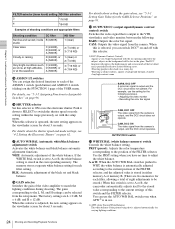
...this selector to ON to the L, M, and H settings can use the AUTO W/B BAL switch even when ATW1) is adjusted automatically for about 3 seconds. When this selector is set to A or B, the camcorder automatically adjusts itself to the stored value corresponding to Assignable Switches" on...on the FUNCTION 1 page of this selector. 1) DCC (Dynamic Contrast Control) Against a very bright background with this switch and the FILTER selector. For example, use . 1) ATW (Auto Tracing White Balance) The white balance of the picture being shot is in either memory A or memory B. (There are L = 0...
...this selector to ON to the L, M, and H settings can use the AUTO W/B BAL switch even when ATW1) is adjusted automatically for about 3 seconds. When this selector is set to A or B, the camcorder automatically adjusts itself to the stored value corresponding to Assignable Switches" on...on the FUNCTION 1 page of this selector. 1) DCC (Dynamic Contrast Control) Against a very bright background with this switch and the FILTER selector. For example, use . 1) ATW (Auto Tracing White Balance) The white balance of the picture being shot is in either memory A or memory B. (There are L = 0...

Operation Manual
Page 25
..." on page 96. When an optional HKDW-702/902R extension board is reset to the original gain. The gain is attached to the camcorder, you can select which makes it possible to control the VTR and camera remotely. For details, see "5-3-2 Selecting Output Signals" on page... 94. When this switch is attached to the camcorder, the camcorder outputs either a down -converted analog composite signal (color) or an SD SDI signal from these connectors using the OUTPUT SEL page of the USER menu. For details, see "5-3-2 Selecting Output Signals" ...
..." on page 96. When an optional HKDW-702/902R extension board is reset to the original gain. The gain is attached to the camcorder, you can select which makes it possible to control the VTR and camera remotely. For details, see "5-3-2 Selecting Output Signals" on page... 94. When this switch is attached to the camcorder, the camcorder outputs either a down -converted analog composite signal (color) or an SD SDI signal from these connectors using the OUTPUT SEL page of the USER menu. For details, see "5-3-2 Selecting Output Signals" ...


