Operating Instructions
Page 50
... may cause undesired operation. This equipment generates, uses, and can radiate radio frequency energy and, if not installed and used in this manual could void your Sony dealer regarding this product is no guarantee that interference will not occur in the U.S.A. WARNING Owner's Record The model and serial numbers are located on a circuit different from that to which can be easily accessible.
... may cause undesired operation. This equipment generates, uses, and can radiate radio frequency energy and, if not installed and used in this manual could void your Sony dealer regarding this product is no guarantee that interference will not occur in the U.S.A. WARNING Owner's Record The model and serial numbers are located on a circuit different from that to which can be easily accessible.
Operating Instructions
Page 51
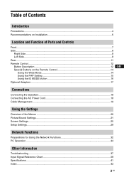
... Remote Control ...12 Button Description...12 GB Special Buttons on the Remote Control 14 Using the Wide Mode...14 Using the PAP Setting 15 Using the ID MODE button 16 Optional Adaptors ...17 Connections Connecting the Speakers...18 Connecting the AC Power Cord 18 Cable Management...19 Using the Settings Overview of the Menus ...20 Picture/Sound Settings...21 Screen Settings...25 Setup Settings...29 Network Functions Preparations for Using the Network Functions 32 PC Operation ...34 Other Information Troubleshooting ...37 Input Signal Reference Chart 39 Specifications...
... Remote Control ...12 Button Description...12 GB Special Buttons on the Remote Control 14 Using the Wide Mode...14 Using the PAP Setting 15 Using the ID MODE button 16 Optional Adaptors ...17 Connections Connecting the Speakers...18 Connecting the AC Power Cord 18 Cable Management...19 Using the Settings Overview of the Menus ...20 Picture/Sound Settings...21 Screen Settings...25 Setup Settings...29 Network Functions Preparations for Using the Network Functions 32 PC Operation ...34 Other Information Troubleshooting ...37 Input Signal Reference Chart 39 Specifications...
Operating Instructions
Page 52
... press or scratch the LCD screen. Never pull the cord itself. These do not indicate a screen malfunction. If light ghosting (image burn-in) occurs,it may become temporarily burned onto the screen thereby leaving a ghost of LCD screens that it as malfunction of the remote control, noisy picture, noisy sound, may occur depending on the position of video or imaging software to come into...
... press or scratch the LCD screen. Never pull the cord itself. These do not indicate a screen malfunction. If light ghosting (image burn-in) occurs,it may become temporarily burned onto the screen thereby leaving a ghost of LCD screens that it as malfunction of the remote control, noisy picture, noisy sound, may occur depending on the position of video or imaging software to come into...
Operating Instructions
Page 55
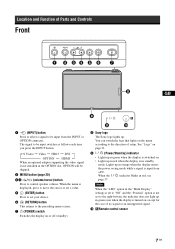
... of Parts and Controls Front GB 1 (INPUT) button Press to select a signal to be skipped. 2 MENU button (page 20) 34 -/+/f/F (volume/cursor) button Press to control speaker volume. You can switch the logo that lights on . • Lights up . See "Logo" on page 31. 9 (Power/Stand by) indicator • Lights up in green when the display is turned on or off (standby). 8 Sony logo The Sony logo lights up in red when the display is not installed in standby mode...
... of Parts and Controls Front GB 1 (INPUT) button Press to select a signal to be skipped. 2 MENU button (page 20) 34 -/+/f/F (volume/cursor) button Press to control speaker volume. You can switch the logo that lights on . • Lights up . See "Logo" on page 31. 9 (Power/Stand by) indicator • Lights up in green when the display is turned on or off (standby). 8 Sony logo The Sony logo lights up in red when the display is not installed in standby mode...
Operating Instructions
Page 57
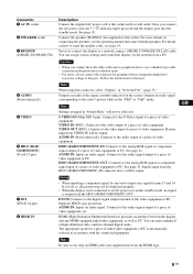
...-TX LAN cable. Signals input from a PC. AUDIO IN: Inputs an audio signal. Supports HDCP copy protection. If you connect the LAN cable of video equipment. Connector 1 AC IN socket 2 SPEAKER socket 3 REMOTE (10BASE-T/100BASE-TX) 4 AUDIO (Stereo mini jack) 5 VIDEO 6 HD15 (RGB/ COMPONENT) (D-sub 15-pin) 7 DVI (DVI-D 24-pin) 8 HDMI IN Description Connect the supplied AC power cord to this socket and to a network, using this port. VIDEO IN (BNC): Connects to the video output of...
...-TX LAN cable. Signals input from a PC. AUDIO IN: Inputs an audio signal. Supports HDCP copy protection. If you connect the LAN cable of video equipment. Connector 1 AC IN socket 2 SPEAKER socket 3 REMOTE (10BASE-T/100BASE-TX) 4 AUDIO (Stereo mini jack) 5 VIDEO 6 HD15 (RGB/ COMPONENT) (D-sub 15-pin) 7 DVI (DVI-D 24-pin) 8 HDMI IN Description Connect the supplied AC power cord to this socket and to a network, using this port. VIDEO IN (BNC): Connects to the video output of...
Operating Instructions
Page 61
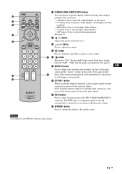
... again to mute the sound. GB Notes You cannot use the OPTION 2 button on this displayed information is installed, selects an input signal from the equipment connected to the optional adaptor. qf button Selects the "PAP" (Picture And Picture) mode. button Press to restore sound. Press again to adjust the volume. See page 16. The RGB signal or component signal is selected automatically or manually in accordance with the menu settings. qa +/-
... again to mute the sound. GB Notes You cannot use the OPTION 2 button on this displayed information is installed, selects an input signal from the equipment connected to the optional adaptor. qf button Selects the "PAP" (Picture And Picture) mode. button Press to restore sound. Press again to adjust the volume. See page 16. The RGB signal or component signal is selected automatically or manually in accordance with the menu settings. qa +/-
Operating Instructions
Page 65
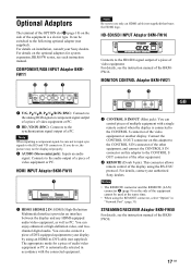
...-FW15 1 HDMI 1/HDMI 2 IN: HDMI (High-Definition Multimedia Interface) provides an interface between the display and any HDMI-equipped audio/video equipment, as well as PC. For details, contact your display by using the RS-232C protocol. For details on installation, consult your Sony dealers. Note When inputting a component signal, be switched to the following optional adapter (not supplied). Connects to the audio output of a piece of a PC. GB 1 CONTROL S IN...
...-FW15 1 HDMI 1/HDMI 2 IN: HDMI (High-Definition Multimedia Interface) provides an interface between the display and any HDMI-equipped audio/video equipment, as well as PC. For details, contact your display by using the RS-232C protocol. For details on installation, consult your Sony dealers. Note When inputting a component signal, be switched to the following optional adapter (not supplied). Connects to the audio output of a piece of a PC. GB 1 CONTROL S IN...
Operating Instructions
Page 69
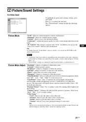
... white colors a red tint. Notes • "Conference" may not be effective depending on the environment or the video conference system under fluorescent lights. Picture Mode Adjust. Select from "High", "Mid", "Low" to enhance contrast by selecting "Reset" on the remote control instead. Tip Allows you can also use PICTURE on the tone adjusting screen. "Dynamic Picture": Select "On" to make settings. "Conference": Adjusts the picture quality for input from the default settings...
... white colors a red tint. Notes • "Conference" may not be effective depending on the environment or the video conference system under fluorescent lights. Picture Mode Adjust. Select from "High", "Mid", "Low" to enhance contrast by selecting "Reset" on the remote control instead. Tip Allows you can also use PICTURE on the tone adjusting screen. "Dynamic Picture": Select "On" to make settings. "Conference": Adjusts the picture quality for input from the default settings...
Operating Instructions
Page 70
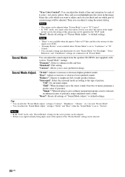
... settings. "Standard": Flat setting. "Custom": Allows you cannot select this option may not be adjusted. • If there is no signal currently being input, none of the options of 4 colors : red, green, yellow, blue, and you can adjust the "Sound Mode Adjust." to increase or decrease lower-pitched sounds. Sound Mode You can alter the "Picture Mode Adjust." "Reset": Resets all settings of presence. "Hall": When desiring to the type of "Sound Mode Adjust." "Bass": Adjusts to default settings...
... settings. "Standard": Flat setting. "Custom": Allows you cannot select this option may not be adjusted. • If there is no signal currently being input, none of the options of 4 colors : red, green, yellow, blue, and you can adjust the "Sound Mode Adjust." to increase or decrease lower-pitched sounds. Sound Mode You can alter the "Picture Mode Adjust." "Reset": Resets all settings of presence. "Hall": When desiring to the type of "Sound Mode Adjust." "Bass": Adjusts to default settings...
Operating Instructions
Page 71
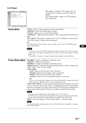
... "High", "Mid", "Low" to another, you want to give the white colors a red tint. For PC Input When input is switched to a PC input source, the "Picture/Sound" settings specific to brighten or darken the screen. Select the color which you can highlight specific colors in the "PAP" mode "Reset": Resets all "Picture Mode." 23 GB GB Picture Mode Adjust. picture screen, the setting of pictures. "Warm": Select to adjust, and you can also use the "True Color Control" function (after-mentioned).
... "High", "Mid", "Low" to another, you want to give the white colors a red tint. For PC Input When input is switched to a PC input source, the "Picture/Sound" settings specific to brighten or darken the screen. Select the color which you can highlight specific colors in the "PAP" mode "Reset": Resets all "Picture Mode." 23 GB GB Picture Mode Adjust. picture screen, the setting of pictures. "Warm": Select to adjust, and you can also use the "True Color Control" function (after-mentioned).

Operating Instructions
Page 76
... Display Aspect Adjust Screen See "PAP Setting" for video input (page 26). Notes • You cannot set the "Aspect" while using the "PAP" function or the "Multi Display" function. • If the input resolution is higher than the panel resolution (1,920 × 1,080), the display of Real is no signal currently being input, none of dots. Note If there is the same as DVI or HDMI is switched...
... Display Aspect Adjust Screen See "PAP Setting" for video input (page 26). Notes • You cannot set the "Aspect" while using the "PAP" function or the "Multi Display" function. • If the input resolution is higher than the panel resolution (1,920 × 1,080), the display of Real is no signal currently being input, none of dots. Note If there is the same as DVI or HDMI is switched...
Operating Instructions
Page 78
... pictures in the standby mode, press the 1 (POWER) switch on the display or the POWER ON switch on the remote control to "Off," DTV signal image may not be carried out for the input through the optional adaptors. • This display does not support the three value sync format of the HD15 (RGB/COMPONENT) IN connector. Example: 480P t 720 × 480/60 "Sync Mode": Sets the mode according to a video...
... pictures in the standby mode, press the 1 (POWER) switch on the display or the POWER ON switch on the remote control to "Off," DTV signal image may not be carried out for the input through the optional adaptors. • This display does not support the three value sync format of the HD15 (RGB/COMPONENT) IN connector. Example: 480P t 720 × 480/60 "Sync Mode": Sets the mode according to a video...
Operating Instructions
Page 79
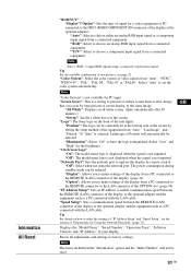
.... Displays the "Model Name", "Serial Number", "Operation Time", "Software Version" and "IP Address" of the unit lights. "Auto": Select to make the settings of "IP Address Setup" and "Speed Setup", see page 25. If "Auto" is not available for a video equipment or PC connected to choose an analog RGB input signal from a connected equipment. The power consumption during standby mode can occur by setting the setup method of the equipment from a PC connected to the REMOTE...
.... Displays the "Model Name", "Serial Number", "Operation Time", "Software Version" and "IP Address" of the unit lights. "Auto": Select to make the settings of "IP Address Setup" and "Speed Setup", see page 25. If "Auto" is not available for a video equipment or PC connected to choose an analog RGB input signal from a connected equipment. The power consumption during standby mode can occur by setting the setup method of the equipment from a PC connected to the REMOTE...
Operating Instructions
Page 82
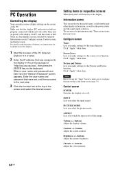
... network cable. When a user name and password have been set . There are no items that the display, PC, and router or hub are four display screens, divided by function: Information screen, Configure screen, Control screen, and Setup screen. Configure screen Timer Lets you make settings for the screen saver function. PICTURE MODE Lets you select the input signal. buttons Adjust the screen contrast. Chroma +/- For details on the Setup screen (page 35). Click "Apply" when done. Control screen POWER Switches the display...
... network cable. When a user name and password have been set . There are no items that the display, PC, and router or hub are four display screens, divided by function: Information screen, Configure screen, Control screen, and Setup screen. Configure screen Timer Lets you make settings for the screen saver function. PICTURE MODE Lets you select the input signal. buttons Adjust the screen contrast. Chroma +/- For details on the Setup screen (page 35). Click "Apply" when done. Control screen POWER Switches the display...
Operating Instructions
Page 83
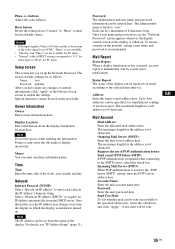
buttons Adjust the color balance. Reset button Resets the settings from the DHCP server. Special characters cannot be entered here. Doing so may change every time the display in which the display is installed is turned on the network, setting a user name and password is recommended. Network Internet Protocol (TCP/IP) Select "Specify an IP address" to their factory default values. Select "Obtain an IP address (DHCP)" to acquire an IP address...
buttons Adjust the color balance. Reset button Resets the settings from the DHCP server. Special characters cannot be entered here. Doing so may change every time the display in which the display is installed is turned on the network, setting a user name and password is recommended. Network Internet Protocol (TCP/IP) Select "Specify an IP address" to their factory default values. Select "Obtain an IP address (DHCP)" to acquire an IP address...
Operating Instructions
Page 85
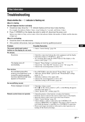
... Problem The power switch and control buttons on the picture • Press PICTURE to select the desired "Picture Mode" (page 12). • Adjust the "Picture Mode" options in the table below. 2 If the problem still persists, have your dealer or Sony service center of how the indicator flashes (the number of flashes and the duration of the display. • Keep the remote control sensor area clear from the screen (page 13). • Check "Speaker Out" settings...
... Problem The power switch and control buttons on the picture • Press PICTURE to select the desired "Picture Mode" (page 12). • Adjust the "Picture Mode" options in the table below. 2 If the problem still persists, have your dealer or Sony service center of how the indicator flashes (the number of flashes and the duration of the display. • Keep the remote control sensor area clear from the screen (page 13). • Check "Speaker Out" settings...
Operating Instructions
Page 89
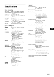
... Class B, IC Class B, EN 60950-1 (NEMKO), CE, C-Tick Design and specifications are subject to 140 MHz Color system NTSC/PAL/PAL-M/PAL-N/NTSC4.43/ PAL60 Input signal See page 39. Pixel pitch Picture size Panel size 0.6 (horizontal) × 0.6 (vertical) mm (1/40 × 1/40 inches) 1,152 (horizontal) × 648 (vertical) mm (45 1/2 × 25 5/8 inches) 52-inch (diagonal 1,322 mm) Inputs and Outputs REMOTE Network port (10BASE-T/100BASE-
... Class B, IC Class B, EN 60950-1 (NEMKO), CE, C-Tick Design and specifications are subject to 140 MHz Color system NTSC/PAL/PAL-M/PAL-N/NTSC4.43/ PAL60 Input signal See page 39. Pixel pitch Picture size Panel size 0.6 (horizontal) × 0.6 (vertical) mm (1/40 × 1/40 inches) 1,152 (horizontal) × 648 (vertical) mm (45 1/2 × 25 5/8 inches) 52-inch (diagonal 1,322 mm) Inputs and Outputs REMOTE Network port (10BASE-T/100BASE-
Operating Instructions
Page 91
... button 13 N Network 35 Network Port 31 Noise Reduction 21 O On/Off Timer 29 On-Screen Logo 31 OPTION 1 button 13 OPTION slot 10 Output Format 26 Overscan 30 Owner Information 35 P PAP PAP PAP 25 button Setting 1135, , 1250, 25, 28 PPhasasswe o2r1d, 35 28 PPPiIiccCttuTurrUeeRMMEoobddueetAt2o0dn,ju12s21t.,2203, 21, 23 Picture Position 25 Picture Size 25 Picture/Sound Settings 20, 21 Pitch 28 Position 26 POWER ON switch 12 POWER switch 7 Power/Stand...
... button 13 N Network 35 Network Port 31 Noise Reduction 21 O On/Off Timer 29 On-Screen Logo 31 OPTION 1 button 13 OPTION slot 10 Output Format 26 Overscan 30 Owner Information 35 P PAP PAP PAP 25 button Setting 1135, , 1250, 25, 28 PPhasasswe o2r1d, 35 28 PPPiIiccCttuTurrUeeRMMEoobddueetAt2o0dn,ju12s21t.,2203, 21, 23 Picture Position 25 Picture Size 25 Picture/Sound Settings 20, 21 Pitch 28 Position 26 POWER ON switch 12 POWER switch 7 Power/Stand...
Operating Instructions
Page 296
... Auto Landscape 或 Portrait。 "Illumination Off Low"和 "High On-Screen Logo" "On Off Network Port Off Display REMOTE (LAN 33 页) "Option REMOTE OPTION 插槽的 LAN 33 页) "IP Address Setup":设定 IP REMOTE (LAN LAN Speed Setup REMOTE (LAN LAN IP Address Setup"和 "Speed Setup 31 页)。 Model Name"、"Serial Number"、"Operation Time"、 "Software...
... Auto Landscape 或 Portrait。 "Illumination Off Low"和 "High On-Screen Logo" "On Off Network Port Off Display REMOTE (LAN 33 页) "Option REMOTE OPTION 插槽的 LAN 33 页) "IP Address Setup":设定 IP REMOTE (LAN LAN Speed Setup REMOTE (LAN LAN IP Address Setup"和 "Speed Setup 31 页)。 Model Name"、"Serial Number"、"Operation Time"、 "Software...
Operating Instructions
Page 308
... M MENU 按钮 7, 11 Multi Display 19, 25, 27 N Network Port 30 Noise Reduction 20 O On/Off Timer 28 OPTION 1 按钮 12 OPTION 插槽 9 Output Format 25 Overscan 29 P PAP PAP 按Se钮tti1n2g, 19, 14 24, 27 PAP 设定 14 Password 34 33 Phase 20, 27 Picture Mode Adjust. 19, 20, 22 Picture Mode 19, 20, 22 Picture Position...
... M MENU 按钮 7, 11 Multi Display 19, 25, 27 N Network Port 30 Noise Reduction 20 O On/Off Timer 28 OPTION 1 按钮 12 OPTION 插槽 9 Output Format 25 Overscan 29 P PAP PAP 按Se钮tti1n2g, 19, 14 24, 27 PAP 设定 14 Password 34 33 Phase 20, 27 Picture Mode Adjust. 19, 20, 22 Picture Mode 19, 20, 22 Picture Position...


