Operating Instructions
Page 54
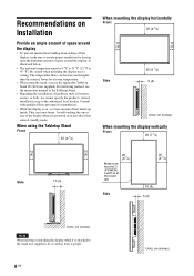
... there can cause burns. Actual installation is attached to the stand (not supplied), do so with qualified Sony personnel for installation. • While the display is powered on , a certain amount of space around the display • To prevent internal heat buildup from sealing off the display, make sure to ensure proper ventilation by leaving open...
... there can cause burns. Actual installation is attached to the stand (not supplied), do so with qualified Sony personnel for installation. • While the display is powered on , a certain amount of space around the display • To prevent internal heat buildup from sealing off the display, make sure to ensure proper ventilation by leaving open...
Operating Instructions
Page 55
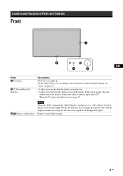
... page 32. • Lights up in red when the display is in standby mode. Location and Function of Parts and Controls Front GB Parts 1 Sony logo 2 1 (Power/Stand by) indicator Description The Sony logo lights up in orange when the display enters the power saving mode while a signal is input from... automatic to the right-bottom, the indicator does not light up in green even when the display is turned on . ...
... page 32. • Lights up in red when the display is in standby mode. Location and Function of Parts and Controls Front GB Parts 1 Sony logo 2 1 (Power/Stand by) indicator Description The Sony logo lights up in orange when the display enters the power saving mode while a signal is input from... automatic to the right-bottom, the indicator does not light up in green even when the display is turned on . ...
Operating Instructions
Page 57
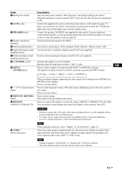
Once you connect the AC power cord and turn on or off (standby). For details on how to install the display stand SU-S01 (not supplied). Screw holes conforming to VESA standard. (Pitch: 400mm × 400mm, Screw: M6) Use these ...Port". (page 32) This is 0W. GB 11 GB Parts 1 Main power switch 2 AC IN socket 3 SPEAKER socket 4 Speaker installation positions 5 Stand installation holes 6 Applicable display stand installation holes 7 Dedicated display stand installation hole cover 8 1 (POWER) switch 9 INPUT/ (ENTER)button 0 +/-/F/f (volume/cursor) button qa MENU/ (RETURN) button qs REMOTE (...
Once you connect the AC power cord and turn on or off (standby). For details on how to install the display stand SU-S01 (not supplied). Screw holes conforming to VESA standard. (Pitch: 400mm × 400mm, Screw: M6) Use these ...Port". (page 32) This is 0W. GB 11 GB Parts 1 Main power switch 2 AC IN socket 3 SPEAKER socket 4 Speaker installation positions 5 Stand installation holes 6 Applicable display stand installation holes 7 Dedicated display stand installation hole cover 8 1 (POWER) switch 9 INPUT/ (ENTER)button 0 +/-/F/f (volume/cursor) button qa MENU/ (RETURN) button qs REMOTE (...
Operating Instructions
Page 89
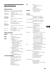
... TFT Active Matrix LCD Panel Display resolution 1,920 dots (horizontal) × 1,080 lines (vertical) Sampling rate 13.5 MHz to 90% (no condensation) Dimensions FWD-S42H1: 972.1 × 565.1 × 125 mm (38 3/8 × 22 1/4 × 4 7/8 inches) 972.1 × 613.6 × 275 mm (38 3/8 × 24 1/4 × 10 7/8 inches) (including optional stand) (w/h/d, excluding projections) FWD...
... TFT Active Matrix LCD Panel Display resolution 1,920 dots (horizontal) × 1,080 lines (vertical) Sampling rate 13.5 MHz to 90% (no condensation) Dimensions FWD-S42H1: 972.1 × 565.1 × 125 mm (38 3/8 × 22 1/4 × 4 7/8 inches) 972.1 × 613.6 × 275 mm (38 3/8 × 24 1/4 × 10 7/8 inches) (including optional stand) (w/h/d, excluding projections) FWD...

Operating Instructions
Page 91
...41 IP Address Setup 32 L Language 21, 30 LED 27 Logo 32 M Mail Account 37 Mail Report 37 Main power switch 11 MENU button Multi Display 2113, 27, 29 Muting button 14 N Network 37 Network Port 32 Noise Reduction 22 O On/Off Timer 30 On-Screen Logo 32 OPTION 1 button..., 22, 24 Picture Position 26 Picture Size 26 Picture/Sound Settings 21, 22 Pitch 29 Position 27 POWER ON switch 13 POWER switch 11 Power/Stand by Indicator 9 R Real 15, 29 REMOTE connector 11 RReemseot t2e3c,on2t5r,ol2s8e,ns2o9r 9 RETURN button 11 RGB/YUV 32 S S VIDEO button 13 SScVreIeDnESOetItNingcson2n1e...
...41 IP Address Setup 32 L Language 21, 30 LED 27 Logo 32 M Mail Account 37 Mail Report 37 Main power switch 11 MENU button Multi Display 2113, 27, 29 Muting button 14 N Network 37 Network Port 32 Noise Reduction 22 O On/Off Timer 30 On-Screen Logo 32 OPTION 1 button..., 22, 24 Picture Position 26 Picture Size 26 Picture/Sound Settings 21, 22 Pitch 29 Position 27 POWER ON switch 13 POWER switch 11 Power/Stand by Indicator 9 R Real 15, 29 REMOTE connector 11 RReemseot t2e3c,on2t5r,ol2s8e,ns2o9r 9 RETURN button 11 RGB/YUV 32 S S VIDEO button 13 SScVreIeDnESOetItNingcson2n1e...


