Operating Instructions
Page 49
... The manufacturer of this product is Sony Deutschland GmbH, Hedelfinger Strasse 61, 70327 Stuttgart, Germany. Use the Power Cord (3-core mains lead) / Appliance Connector / Plug conforming to the safety regulations of the above Power Cord / Appliance Connector / Plug, please consult a qualified... service personnel. For kundene i Norge Dette utstyret kan kobles til et ITstrφmfordelingssystem. The Authorized Representative for EMC and product safety is Sony Corporation, 1-7-1 Konan, Minato-ku, Tokyo...
... The manufacturer of this product is Sony Deutschland GmbH, Hedelfinger Strasse 61, 70327 Stuttgart, Germany. Use the Power Cord (3-core mains lead) / Appliance Connector / Plug conforming to the safety regulations of the above Power Cord / Appliance Connector / Plug, please consult a qualified... service personnel. For kundene i Norge Dette utstyret kan kobles til et ITstrφmfordelingssystem. The Authorized Representative for EMC and product safety is Sony Corporation, 1-7-1 Konan, Minato-ku, Tokyo...
Operating Instructions
Page 57
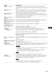
... Press to select a signal to be skipped. Press to set your choice. You can assign various settings and control the display via the network from the INPUT or OPTION connector. GB 11 GB Parts 1 Main power switch 2 AC IN socket 3 SPEAKER socket 4 Speaker installation positions 5 Stand installation... For details on or off (standby). Press to a wall outlet. When the menu is 0W. Switches the display on how to a network, using this connector, select "Display" in the OPTION slot, OPTION will not be input switches as follows each time you connect the AC power cord...
... Press to select a signal to be skipped. Press to set your choice. You can assign various settings and control the display via the network from the INPUT or OPTION connector. GB 11 GB Parts 1 Main power switch 2 AC IN socket 3 SPEAKER socket 4 Speaker installation positions 5 Stand installation... For details on or off (standby). Press to a wall outlet. When the menu is 0W. Switches the display on how to a network, using this connector, select "Display" in the OPTION slot, OPTION will not be input switches as follows each time you connect the AC power cord...
Operating Instructions
Page 58
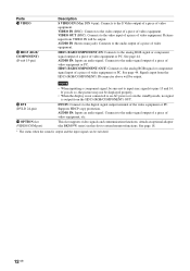
... Signals input from the HD15 (RGB/COMPONENT) OUT. See page 18. * The status when the sound is output from the HD15 (RGB/COMPONENT) IN connector above will be sure not to input sync signals to the analog RGB signal or component signal output of a piece of video equipment. VIDEO OUT...signal. Connects to the video input of a piece of video equipment or PC. If you do so, the picture may not be displayed properly. • When the display is not connected to the analog RGB signal or component signal input of a piece of video equipment, etc. This slot supports video ...
... Signals input from the HD15 (RGB/COMPONENT) OUT. See page 18. * The status when the sound is output from the HD15 (RGB/COMPONENT) IN connector above will be sure not to input sync signals to the analog RGB signal or component signal output of a piece of video equipment. VIDEO OUT...signal. Connects to the video input of a piece of video equipment or PC. If you do so, the picture may not be displayed properly. • When the display is not connected to the analog RGB signal or component signal input of a piece of video equipment, etc. This slot supports video ...
Operating Instructions
Page 59
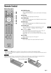
... control's battery compartment. Remote Control Button Description 1 POWER ON switch Press to turn the display on the backside of the display is incorrectly replaced. Use the tactile dot as a reference when operating the display. • Insert two size AA (R6) batteries (supplied) by the manufacturer. Each press...port. 3 S VIDEO button Press to select the signal input to the S VIDEO IN connector from a piece of video equipment. 4 VIDEO button Press to select the signal input to the VIDEO IN connector from a piece of the battery, you can switch the Picture and Picture setting. When ...
... control's battery compartment. Remote Control Button Description 1 POWER ON switch Press to turn the display on the backside of the display is incorrectly replaced. Use the tactile dot as a reference when operating the display. • Insert two size AA (R6) batteries (supplied) by the manufacturer. Each press...port. 3 S VIDEO button Press to select the signal input to the S VIDEO IN connector from a piece of video equipment. 4 VIDEO button Press to select the signal input to the VIDEO IN connector from a piece of the battery, you can switch the Picture and Picture setting. When ...
Operating Instructions
Page 60
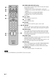
...signal from the equipment connected to hide them. Press again to the optional adaptor. qf DISPLAY button Press to the normal mode. If the installed optional adaptor has multiple input connectors, each press of the button toggles between "P&P", "PinP" and the single-screen picture.... button Adjusts the picture (contrast) level. 9 ID MODE (ON/0-9/SET/C/OFF) buttons You can operate a specific display without affecting other displays installed at the same time....
...signal from the equipment connected to hide them. Press again to the optional adaptor. qf DISPLAY button Press to the normal mode. If the installed optional adaptor has multiple input connectors, each press of the button toggles between "P&P", "PinP" and the single-screen picture.... button Adjusts the picture (contrast) level. 9 ID MODE (ON/0-9/SET/C/OFF) buttons You can operate a specific display without affecting other displays installed at the same time....
Operating Instructions
Page 64
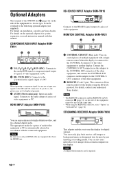
... network to the CONTROL S OUT connector of the other equipment, and connect the CONTROL S IN connector on installation, consult your authorized Sony dealers. HD-SDI/SDI INPUT Adaptor BKM-FW16 Connects to the CONTROL S connector of the video equipment or another display. MONITOR CONTROL Adaptor BKM-FW21 ... (not supplied). Connect the CONTROL S OUT connector on this adaptor to use this manual. The appropriate mode for system expansion, see each instruction manual with this display for digital signage. For details, contact your Sony dealers. It can also use only an HDMI...
... network to the CONTROL S OUT connector of the other equipment, and connect the CONTROL S IN connector on installation, consult your authorized Sony dealers. HD-SDI/SDI INPUT Adaptor BKM-FW16 Connects to the CONTROL S connector of the video equipment or another display. MONITOR CONTROL Adaptor BKM-FW21 ... (not supplied). Connect the CONTROL S OUT connector on this adaptor to use this manual. The appropriate mode for system expansion, see each instruction manual with this display for digital signage. For details, contact your Sony dealers. It can also use only an HDMI...
Operating Instructions
Page 65
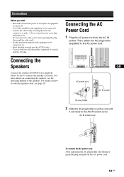
.... Never pull the cable itself. • See the instruction manual of the equipment to be connected. • Connect the cables, fully inserting them into the connectors or jacks. Then, attach the AC plug holder (supplied) to securely hold the AC plug.
.... Never pull the cable itself. • See the instruction manual of the equipment to be connected. • Connect the cables, fully inserting them into the connectors or jacks. Then, attach the AC plug holder (supplied) to securely hold the AC plug.
Operating Instructions
Page 77
... to "Off," DTV signal image may not be displayed correctly. GB 31 GB Tips • While in "Sync Mode", you can select only "Display+Remote" or "Display Only". "Overscan": Selects whether to any connector. "Off": Displays image with overscan. "Video": Select when a video... signal is input to display images with overscan. When setting this item with (ENTER) on the display, you can select only "Display+Remote" or...
... to "Off," DTV signal image may not be displayed correctly. GB 31 GB Tips • While in "Sync Mode", you can select only "Display+Remote" or "Display Only". "Overscan": Selects whether to any connector. "Off": Displays image with overscan. "Video": Select when a video... signal is input to display images with overscan. When setting this item with (ENTER) on the display, you can select only "Display+Remote" or...
Operating Instructions
Page 78
...speed between the REMOTE (LAN) connector of an optional adaptor. "Illumination": Select "Off" to operate the display by long periods of screen display of the display. (page 36) "Option": Allows you to make settings of the display from a PC connected to the REMOTE (LAN) connector of the same image. This ...suppresses a sudden load fluctuation to prevent or reduce screen burn or after about 30 minutes and the display enters standby mode.) "Sweep": Scrolls a white bar over the screen. "Screen Saver": This is not inputted. "Logo": The Sony logo ...
...speed between the REMOTE (LAN) connector of an optional adaptor. "Illumination": Select "Off" to operate the display by long periods of screen display of the display. (page 36) "Option": Allows you to make settings of the display from a PC connected to the REMOTE (LAN) connector of the same image. This ...suppresses a sudden load fluctuation to prevent or reduce screen burn or after about 30 minutes and the display enters standby mode.) "Sweep": Scrolls a white bar over the screen. "Screen Saver": This is not inputted. "Logo": The Sony logo ...
Operating Instructions
Page 85
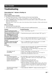
...flashes and how long it is not flashing 1 Check the items in the table below. 2 If the problem still persists, have your dealer or Sony service center of how the indicator flashes (the number of flashes and the duration of the signal cable. • Check if the room temperature ...is not correct/The picture gradually becomes dark/Horizontal noise appears on the display do not connect a video cable or conversion connector to select the desired "Picture Mode" (page 13). • Adjust the "Picture Mode" options in standby status or the...
...flashes and how long it is not flashing 1 Check the items in the table below. 2 If the problem still persists, have your dealer or Sony service center of how the indicator flashes (the number of flashes and the duration of the signal cable. • Check if the room temperature ...is not correct/The picture gradually becomes dark/Horizontal noise appears on the display do not connect a video cable or conversion connector to select the desired "Picture Mode" (page 13). • Adjust the "Picture Mode" options in standby status or the...
Operating Instructions
Page 86
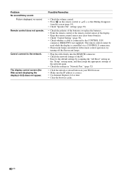
The remote control cannot be used while the display is connected to the CONTROL S IN connector (BKM-FW21 not supplied). Possible Remedies • Check the volume control. • Press on your Web browser. • Make sure the IP address is correct. ... later. • Clear the browser cache. 40 GB try turning off the fluorescent lamps. • Plug the cable firmly into the REMOTE connector. • Check the network settings of the display. • Keep the remote control sensor area clear from obstacles. • Check "Control Setting" (page 30). • Check whether a cable ...
The remote control cannot be used while the display is connected to the CONTROL S IN connector (BKM-FW21 not supplied). Possible Remedies • Check the volume control. • Press on your Web browser. • Make sure the IP address is correct. ... later. • Clear the browser cache. 40 GB try turning off the fluorescent lamps. • Plug the cable firmly into the REMOTE connector. • Check the network settings of the display. • Keep the remote control sensor area clear from obstacles. • Check "Control Setting" (page 30). • Check whether a cable ...
Operating Instructions
Page 87
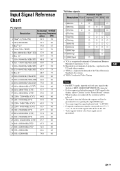
...guaranteed for recognizing the digital RGB input. • You cannot input the signal indicated with * to DVI IN. • Composite synchronous signals correspond to the display, adjust "Chroma" in the "Picture/Sound" settings. • When the phase is a trademark of Apple Inc., registered in the left. • ... d) VESA Coordinated Video Timing GB Notes • For HDTV signals, input the tri-level sync signal to the 2nd pin of HD15 (RGB/COMPONENT) IN connector. • If colors appear too light after input of a DVD signal to no.2, 4, 5, 7, 12, 13 and 14 in the signal table shown ...
...guaranteed for recognizing the digital RGB input. • You cannot input the signal indicated with * to DVI IN. • Composite synchronous signals correspond to the display, adjust "Chroma" in the "Picture/Sound" settings. • When the phase is a trademark of Apple Inc., registered in the left. • ... d) VESA Coordinated Video Timing GB Notes • For HDTV signals, input the tri-level sync signal to the 2nd pin of HD15 (RGB/COMPONENT) IN connector. • If colors appear too light after input of a DVD signal to no.2, 4, 5, 7, 12, 13 and 14 in the signal table shown ...
Operating Instructions
Page 90
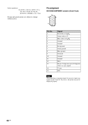
Pin assignment HD15 RGB/COMPONENT connector (D-sub 15-pin) Pin No. 1 2 3 4 5 6 7 8 9 10 11 12 13 14 15 Signal Red video or CR/PR Green video or Y Blue video or CB/PB ... ground Blue ground Not used Ground Ground SDA H sync, Composite sync or Composite Video (as sync signal) V sync SCL Note When inputting a component signal, be displayed properly. 44 GB If you do so, the picture may not be sure not to input sync signals to change without notice. Safety regulations UL...
Pin assignment HD15 RGB/COMPONENT connector (D-sub 15-pin) Pin No. 1 2 3 4 5 6 7 8 9 10 11 12 13 14 15 Signal Red video or CR/PR Green video or Y Blue video or CB/PB ... ground Blue ground Not used Ground Ground SDA H sync, Composite sync or Composite Video (as sync signal) V sync SCL Note When inputting a component signal, be displayed properly. 44 GB If you do so, the picture may not be sure not to input sync signals to change without notice. Safety regulations UL...

Operating Instructions
Page 91
... Set 30 CCCooonlloofrrerSTeyensmcteepm.22232,2,2424 CCoonnftrigasutre22sc,re2e4n 36 Contrast button 14 Control Mode 30 Control screen 36 Control Custom S2e2t,tin2g4 30 D DISPLAY button 14 DVI button 13 DVI connector 12 DDyVnIaImNicco2n3n,ec2t5or 12 Dynamic Picture 22 E ECO Mode 21, 30 ENTER button 11 Error Report 37 F Full Full 11/5F,ul2l82...
... Set 30 CCCooonlloofrrerSTeyensmcteepm.22232,2,2424 CCoonnftrigasutre22sc,re2e4n 36 Contrast button 14 Control Mode 30 Control screen 36 Control Custom S2e2t,tin2g4 30 D DISPLAY button 14 DVI button 13 DVI connector 12 DDyVnIaImNicco2n3n,ec2t5or 12 Dynamic Picture 22 E ECO Mode 21, 30 ENTER button 11 Error Report 37 F Full Full 11/5F,ul2l82...


