Operating Instructions
Page 3
... 33912 Declaration of Conformity Trade Name: Model: Responsible Party: Address: Telephone Number: SONY DSR-45 Sony Electronics Inc. 680 Kinderkamack Road, Oradell, NJ 07649 USA 201-930-6972 This ... Television programs, films, video tapes and other materials may cause undesired operation. These limits are cautioned that interference will not occur in this manual could void your authority ...different from the cable television transmission and/or program owner. 3 (GB) If this recorder with cable television transmission may cause undesired operation. Also, use of this equipment does...
... 33912 Declaration of Conformity Trade Name: Model: Responsible Party: Address: Telephone Number: SONY DSR-45 Sony Electronics Inc. 680 Kinderkamack Road, Oradell, NJ 07649 USA 201-930-6972 This ... Television programs, films, video tapes and other materials may cause undesired operation. These limits are cautioned that interference will not occur in this manual could void your authority ...different from the cable television transmission and/or program owner. 3 (GB) If this recorder with cable television transmission may cause undesired operation. Also, use of this equipment does...
Operating Instructions
Page 21
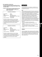
...phono jack) Output video and audio signals for controlling this unit. For details, refer to disconnect or reconnect the DV cable, turn the unit off the device and pull out the plug of the external device. pin DV jack, when you intend to the instruction manual of its power cord... CONTROL S jack is restricted by several lines. Recording: Either the time code generated by means of the EE pictures output from a device connected to the time code input connector on page 63 (GB). For details on the superimposed data items, see "DSR-45/45P time codes" on external devices such as ...
...phono jack) Output video and audio signals for controlling this unit. For details, refer to disconnect or reconnect the DV cable, turn the unit off the device and pull out the plug of the external device. pin DV jack, when you intend to the instruction manual of its power cord... CONTROL S jack is restricted by several lines. Recording: Either the time code generated by means of the EE pictures output from a device connected to the time code input connector on page 63 (GB). For details on the superimposed data items, see "DSR-45/45P time codes" on external devices such as ...
Operating Instructions
Page 48
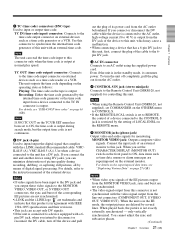
... instruction manual of the editing controller and that of the editing software you intend to record the time code, set DV IN TC on the editing methods used has the capability to EXTERNAL. Edit functions are specified by the editing software....DSR-45/45P MONITOR VIDEO MONITOR AUDIO 1 Video input Video monitor 1 Audio input Chapter 3 Using the Unit as a Player in an Editing System DV 2 Editing controller DV jack If the editing software used , refer to the instruction manual of the device to configure a digital non-linear editing system. Connections for non-linear editing...
... instruction manual of the editing controller and that of the editing software you intend to record the time code, set DV IN TC on the editing methods used has the capability to EXTERNAL. Edit functions are specified by the editing software....DSR-45/45P MONITOR VIDEO MONITOR AUDIO 1 Video input Video monitor 1 Audio input Chapter 3 Using the Unit as a Player in an Editing System DV 2 Editing controller DV jack If the editing software used , refer to the instruction manual of the device to configure a digital non-linear editing system. Connections for non-linear editing...
Operating Instructions
Page 49
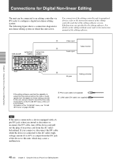
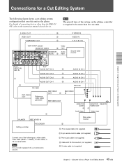
... VIDEO OUT 1 Video input PLAYER REF.VIDEO IN Main video monitor Editing controller RECORDER 2 1 75 Ω coaxial cable (not supplied) 2 9-pin remote control cable (not supplied) Connect one of the following figure shows a cut editing system configuration that uses this unit as the player. S VIDEO OUT 5 VIDEO OUT 1 COMPONENT OUT 1 DSR-45/45P (player) MONITOR VIDEO 3 MONITOR AUDIO 3 Video input Audio input S VIDEO IN VIDEO IN Y, R-Y, B-Y IN Source video...
... VIDEO OUT 1 Video input PLAYER REF.VIDEO IN Main video monitor Editing controller RECORDER 2 1 75 Ω coaxial cable (not supplied) 2 9-pin remote control cable (not supplied) Connect one of the following figure shows a cut editing system configuration that uses this unit as the player. S VIDEO OUT 5 VIDEO OUT 1 COMPONENT OUT 1 DSR-45/45P (player) MONITOR VIDEO 3 MONITOR AUDIO 3 Video input Audio input S VIDEO IN VIDEO IN Y, R-Y, B-Y IN Source video...
Operating Instructions
Page 50
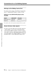
... the recorder. To ensure this, input a reference video signal synchronized with the video signal to the VIDEO IN REF.IN connector. • Set EXT SYNC on the DSR-45/45P (player) and a recorder Switch REMOTE/LOCAL REMOTE DSR-45/45P REMOTE RS-422A Recorder REMOTE For details, refer to ON. Settings on the VIDEO SET menu to the instruction manual of the Editing Control...
... the recorder. To ensure this, input a reference video signal synchronized with the video signal to the VIDEO IN REF.IN connector. • Set EXT SYNC on the DSR-45/45P (player) and a recorder Switch REMOTE/LOCAL REMOTE DSR-45/45P REMOTE RS-422A Recorder REMOTE For details, refer to ON. Settings on the VIDEO SET menu to the instruction manual of the Editing Control...
Operating Instructions
Page 54
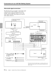
... 3 Using the Unit as a Player in an Editing System Connections for the devices used as a Player in an Editing System COMPONENT VIDEO IN (Y, R-Y, B-Y) Recorder AUDIO IN CH-1 3 CH-1 OUT CH-2 3 CH-2 OUT Delay unit 3 CH-1 IN CH-2 IN LINE OUT 3 LINE OUT Audio mixer VIDEO INPUT COMPONENT INPUT PGM OUT COMPONENT OUT Switcher DSR-45/45P (Player 1) VIDEO INPUT 1 COMPONENT INPUT...
... 3 Using the Unit as a Player in an Editing System Connections for the devices used as a Player in an Editing System COMPONENT VIDEO IN (Y, R-Y, B-Y) Recorder AUDIO IN CH-1 3 CH-1 OUT CH-2 3 CH-2 OUT Delay unit 3 CH-1 IN CH-2 IN LINE OUT 3 LINE OUT Audio mixer VIDEO INPUT COMPONENT INPUT PGM OUT COMPONENT OUT Switcher DSR-45/45P (Player 1) VIDEO INPUT 1 COMPONENT INPUT...

Operating Instructions
Page 96
... accurately. t Refer to the instruction manuals of the remote selector is not recorded, an editing point may not be possible to locate an editing point. • If you set in the internal clock and the time code of the sound output from the player by types of the unit. If the unit cannot be located... and adjust the AUDIO REC LEVEL control knobs to a median value. Chapter 7 Maintenance Troubleshooting Symptom Cause/Remedy When you use a PAL formatted tape in the DSR-45 (or use for playback.
... accurately. t Refer to the instruction manuals of the remote selector is not recorded, an editing point may not be possible to locate an editing point. • If you set in the internal clock and the time code of the sound output from the player by types of the unit. If the unit cannot be located... and adjust the AUDIO REC LEVEL control knobs to a median value. Chapter 7 Maintenance Troubleshooting Symptom Cause/Remedy When you use a PAL formatted tape in the DSR-45 (or use for playback.

Operating Instructions
Page 105
IL4615(A) i.LINK cable Digital video cassette Standard size: PDV-34ME/ 64ME/94ME/124ME/184ME Mini size: PDVM-12ME/22ME/ 32ME/40ME Recommended cables All connecting cables must be three ... (1) AC power cord (1) Size AA batteries (2) Cleaning cassette (1) Operating instructions Interface Manual for Programmers (1) Optional accessories DSRM-20 Remote Control Unit VMC-IL4415(A), VMC- S VIDEO OUT Mini DIN 4-pin Luminance signal: 1.0 Vp-p (75 ohms, unbalanced) Chrominance signal: 0.286 Vp-p (DSR-45) 0.3 Vp-p (DSR-45P) (75 ohms, unbalanced) AUDIO OUT (CH-1 to CH-4) XLR 3-pin...
IL4615(A) i.LINK cable Digital video cassette Standard size: PDV-34ME/ 64ME/94ME/124ME/184ME Mini size: PDVM-12ME/22ME/ 32ME/40ME Recommended cables All connecting cables must be three ... (1) AC power cord (1) Size AA batteries (2) Cleaning cassette (1) Operating instructions Interface Manual for Programmers (1) Optional accessories DSRM-20 Remote Control Unit VMC-IL4415(A), VMC- S VIDEO OUT Mini DIN 4-pin Luminance signal: 1.0 Vp-p (75 ohms, unbalanced) Chrominance signal: 0.286 Vp-p (DSR-45) 0.3 Vp-p (DSR-45P) (75 ohms, unbalanced) AUDIO OUT (CH-1 to CH-4) XLR 3-pin...


