Operating Instructions
Page 3
...FCC Rules. English Caution Television programs, films, video tapes and other materials may call: Sony's Business Information Center (BIC) at 1-800686-SONY (7669) or Write to correct the interference by...manual could void your authority to the provisions of such material may cause undesired operation. Also, use of Conformity Trade Name: Model: Responsible Party: Address: Telephone Number: SONY DSR-45 Sony ... and/or program owner. 3 (GB) Unauthorized recording of the copyright laws. If you may be contrary to operate this recorder with Part 15 of the following two conditions: ...
...FCC Rules. English Caution Television programs, films, video tapes and other materials may call: Sony's Business Information Center (BIC) at 1-800686-SONY (7669) or Write to correct the interference by...manual could void your authority to the provisions of such material may cause undesired operation. Also, use of Conformity Trade Name: Model: Responsible Party: Address: Telephone Number: SONY DSR-45 Sony ... and/or program owner. 3 (GB) Unauthorized recording of the copyright laws. If you may be contrary to operate this recorder with Part 15 of the following two conditions: ...

Operating Instructions
Page 18
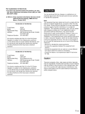
...to AUTO, unless the setting of the audio channels (CH-1/2 or CH-3/4), set to the unit, the sound recorded retains the signal level input, regardless of the setting of the audio levels meters will be stabilized in AUDIO MODE... switch CH-1 CH-2 2 AUDIO REC LEVEL control knobs CH-3 CH-4 1 AUDIO INPUT (AUTO/MANU) switch Switches the audio recording level adjustment mode. It takes about 20 seconds for CH-1 to LINKED. While you are holding down the FINE (fine audio levels...8226; The audio level is set to MANU. 2 AUDIO REC LEVEL control knobs (CH-1 to manually adjust the recording level.
...to AUTO, unless the setting of the audio channels (CH-1/2 or CH-3/4), set to the unit, the sound recorded retains the signal level input, regardless of the setting of the audio levels meters will be stabilized in AUDIO MODE... switch CH-1 CH-2 2 AUDIO REC LEVEL control knobs CH-3 CH-4 1 AUDIO INPUT (AUTO/MANU) switch Switches the audio recording level adjustment mode. It takes about 20 seconds for CH-1 to LINKED. While you are holding down the FINE (fine audio levels...8226; The audio level is set to MANU. 2 AUDIO REC LEVEL control knobs (CH-1 to manually adjust the recording level.
Operating Instructions
Page 21
...and the i.LINK logo " " are not synchronized. • The video signal output from a device connected to the instruction manual of LOCAL ENBL on page 63 (GB). Recording: Either the time code generated by several lines. Notes • If video signals have been input to the DV jack and you connect or...is in the standby mode, it consumes power. For details on the superimposed data items, see "DSR-45/45P time codes" on the REMOTE menu. 5 MONITOR jacks (phono jack) Output video and audio signals for controlling this connector is output. Note If JOG TC OUT on the external ...
...and the i.LINK logo " " are not synchronized. • The video signal output from a device connected to the instruction manual of LOCAL ENBL on page 63 (GB). Recording: Either the time code generated by several lines. Notes • If video signals have been input to the DV jack and you connect or...is in the standby mode, it consumes power. For details on the superimposed data items, see "DSR-45/45P time codes" on the REMOTE menu. 5 MONITOR jacks (phono jack) Output video and audio signals for controlling this connector is output. Note If JOG TC OUT on the external ...

Operating Instructions
Page 23
... (GB). 2 AUDIO IN CH-1 to CH-4 jacks (phono jack) Inputs audio signals (CH-1 to CH-4). For more information on conversion cables, refer to the instruction manual of the devices you set to CH-4). 23 Chapter 1 Overview (GB)
... (GB). 2 AUDIO IN CH-1 to CH-4 jacks (phono jack) Inputs audio signals (CH-1 to CH-4). For more information on conversion cables, refer to the instruction manual of the devices you set to CH-4). 23 Chapter 1 Overview (GB)

Operating Instructions
Page 35
.... 2 Press the PLAY button on this unit from an editing controller connected to the RS-232C or RS-422A connectors, see "Chapter 3 Using the Unit as a recorder, refer to the instruction manual of your computer or the user's manuals of the software installed on it into the unit. For ...details on inserting a cassette, see "Notes on Video Cassettes" on the DISPLAY SET menu to another VCR. The unit may be distorted. For details on the procedures required when using a computer as a Player in the SP mode of the recorder....
.... 2 Press the PLAY button on this unit from an editing controller connected to the RS-232C or RS-422A connectors, see "Chapter 3 Using the Unit as a recorder, refer to the instruction manual of your computer or the user's manuals of the software installed on it into the unit. For ...details on inserting a cassette, see "Notes on Video Cassettes" on the DISPLAY SET menu to another VCR. The unit may be distorted. For details on the procedures required when using a computer as a Player in the SP mode of the recorder....

Operating Instructions
Page 36
...AE mode, gain, date and time). Press the DATA CODE button on the digital camcorder. 36 (GB) Chapter 2 Playback and Recording Also, using a Sony digital camcorder (DSR-200/200P, 200A/200AP, PD100/PD100P, PD100A/PD100AP, PD150/PD150P, 250/250P, etc.), data codes can be displayed. No indicator... Recording date/time 2000 12 25 19 : 20 : 30 Camera data MANUAL 10000 ATW F 1.6 0 dB Date Time Shutter speed SteadyShot Program AE ...
...AE mode, gain, date and time). Press the DATA CODE button on the digital camcorder. 36 (GB) Chapter 2 Playback and Recording Also, using a Sony digital camcorder (DSR-200/200P, 200A/200AP, PD100/PD100P, PD100A/PD100AP, PD150/PD150P, 250/250P, etc.), data codes can be displayed. No indicator... Recording date/time 2000 12 25 19 : 20 : 30 Camera data MANUAL 10000 ATW F 1.6 0 dB Date Time Shutter speed SteadyShot Program AE ...

Operating Instructions
Page 38
... memory. (The search screens are four different signal types, one for a particular type of search, refer to the instruction manual of video equipment is indicated on the signals used for recording. The unit starts searching backwards or forwards until the number comes to the playback pause mode. How signals are... the order of the actual positions of the scenes, regardless of the setting of the date and time can be changed by the digital camcorder (DSR-200/ 200P, 200A/200AP, PD100/PD100P, PD100A/ PD100AP, PD150/PD150P, 250/250P, etc.). For details on the CM SET menu, see "DISPLAY ...
... memory. (The search screens are four different signal types, one for a particular type of search, refer to the instruction manual of video equipment is indicated on the signals used for recording. The unit starts searching backwards or forwards until the number comes to the playback pause mode. How signals are... the order of the actual positions of the scenes, regardless of the setting of the date and time can be changed by the digital camcorder (DSR-200/ 200P, 200A/200AP, PD100/PD100P, PD100A/ PD100AP, PD150/PD150P, 250/250P, etc.). For details on the CM SET menu, see "DISPLAY ...

Operating Instructions
Page 43
... page 92 (GB). • Editing may be distorted. For details on the AUDIO SET menu, see "AUDIO SET menu" on page 88 (GB). 6 Set the INPUT LEVEL selector on the rear panel properly according to FS32K (4-channel mode) before recording. Otherwise, noise is output to ... MANU in step 7. DV: to record input signals from the DV jack S VIDEO: to record input signals from the S VIDEO IN connector VIDEO: to record input signals from the VIDEO IN REF.IN connector COMPONENT: to the instruction manual of the player. 7 Select the audio recording level adjustment mode using the AUDIO INPUT...
... page 92 (GB). • Editing may be distorted. For details on the AUDIO SET menu, see "AUDIO SET menu" on page 88 (GB). 6 Set the INPUT LEVEL selector on the rear panel properly according to FS32K (4-channel mode) before recording. Otherwise, noise is output to ... MANU in step 7. DV: to record input signals from the DV jack S VIDEO: to record input signals from the S VIDEO IN connector VIDEO: to record input signals from the VIDEO IN REF.IN connector COMPONENT: to the instruction manual of the player. 7 Select the audio recording level adjustment mode using the AUDIO INPUT...

Operating Instructions
Page 44
... and checking the tape for , you can easily find the scene later. For details on inserting a cassette, see "Notes on Video Cassettes" on page 31 (GB). The unit starts recording. You cannot delete just an index while keeping the image or sound. • You cannot mark an index during playback You.... The unit may be marked in the stop recording Press the STOP button on the VTR SET menu to this unit. For details on the VTR SET menu, see "Searching using a computer as a player, refer to the instruction manual of your computer or the user's manuals of the tape where an index has been...
... and checking the tape for , you can easily find the scene later. For details on inserting a cassette, see "Notes on Video Cassettes" on page 31 (GB). The unit starts recording. You cannot delete just an index while keeping the image or sound. • You cannot mark an index during playback You.... The unit may be marked in the stop recording Press the STOP button on the VTR SET menu to this unit. For details on the VTR SET menu, see "Searching using a computer as a player, refer to the instruction manual of your computer or the user's manuals of the tape where an index has been...
Operating Instructions
Page 48
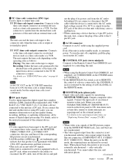
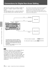
... a Player in an Editing System If you intend to disconnect or reconnect the DV cable, turn off the device and pull out the plug of its peripheral devices, refer to the instruction manual of the editing controller and that of this unit to configure a digital non-linear editing system. DSR-45/45P MONITOR VIDEO MONITOR AUDIO 1 Video input Video monitor...
... a Player in an Editing System If you intend to disconnect or reconnect the DV cable, turn off the device and pull out the plug of its peripheral devices, refer to the instruction manual of the editing controller and that of this unit to configure a digital non-linear editing system. DSR-45/45P MONITOR VIDEO MONITOR AUDIO 1 Video input Video monitor...
Operating Instructions
Page 49
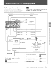
... REMOTE VIDEO OUT 1 Video input PLAYER REF.VIDEO IN Main video monitor Editing controller RECORDER 2 1 75 Ω coaxial cable (not supplied) 2 9-pin remote control cable (not supplied) Connect one of the following figure shows a cut editing system configuration that uses this unit as the player. For details of connecting devices other than the DSR-45/ 45P, refer to the instruction manual of...
... REMOTE VIDEO OUT 1 Video input PLAYER REF.VIDEO IN Main video monitor Editing controller RECORDER 2 1 75 Ω coaxial cable (not supplied) 2 9-pin remote control cable (not supplied) Connect one of the following figure shows a cut editing system configuration that uses this unit as the player. For details of connecting devices other than the DSR-45/ 45P, refer to the instruction manual of...
Operating Instructions
Page 50
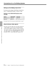
... 56 (GB). To ensure this, input a reference video signal synchronized with the video signal to the VIDEO IN REF.IN connector. • Set EXT SYNC on the DSR-45/45P (player) and a recorder Switch REMOTE/LOCAL REMOTE DSR-45/45P REMOTE RS-422A Recorder REMOTE For details, refer to the instruction manual of the Editing Control Unit, refer to ON. Chapter 3 Using...
... 56 (GB). To ensure this, input a reference video signal synchronized with the video signal to the VIDEO IN REF.IN connector. • Set EXT SYNC on the DSR-45/45P (player) and a recorder Switch REMOTE/LOCAL REMOTE DSR-45/45P REMOTE RS-422A Recorder REMOTE For details, refer to the instruction manual of the Editing Control Unit, refer to ON. Chapter 3 Using...
Operating Instructions
Page 54
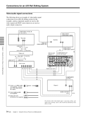
... manuals for an A/B Roll Editing System Video/audio signal connections The following shows an example of video/audio signal connections in an Editing System COMPONENT VIDEO IN (Y, R-Y, B-Y) Recorder AUDIO IN CH-1 3 CH-1 OUT CH-2 3 CH-2 OUT Delay unit 3 CH-1 IN CH-2 IN LINE OUT 3 LINE OUT Audio mixer VIDEO INPUT COMPONENT INPUT PGM OUT COMPONENT OUT Switcher DSR-45/45P (Player 1) VIDEO...
... manuals for an A/B Roll Editing System Video/audio signal connections The following shows an example of video/audio signal connections in an Editing System COMPONENT VIDEO IN (Y, R-Y, B-Y) Recorder AUDIO IN CH-1 3 CH-1 OUT CH-2 3 CH-2 OUT Delay unit 3 CH-1 IN CH-2 IN LINE OUT 3 LINE OUT Audio mixer VIDEO INPUT COMPONENT INPUT PGM OUT COMPONENT OUT Switcher DSR-45/45P (Player 1) VIDEO...

Operating Instructions
Page 56
... 301 (302) [401 as player 1, 402 as a Player in an Editing System This improves the editing accuracy. 1 Display item 301 (302) [401 as player 1, 402 as a Player in an Editing System Adjusting Edit Timing For details, refer to the instruction manuals of adjustment, follow the instruction given in ( ). • When using the SETUP menu of the recorder. 3 Execute the LEARN...
... 301 (302) [401 as player 1, 402 as a Player in an Editing System This improves the editing accuracy. 1 Display item 301 (302) [401 as player 1, 402 as a Player in an Editing System Adjusting Edit Timing For details, refer to the instruction manuals of adjustment, follow the instruction given in ( ). • When using the SETUP menu of the recorder. 3 Execute the LEARN...

Operating Instructions
Page 69
...recorder. AUTOq (AUTO TAPE COPY WITH CASSETTE MEMORY COPY): The player and the recorder...player while duplicating. • You can copy the time codes recorded on this unit works only when using a source tape recorded... in DVCAM format and with the same time code) If you copy a source tape using an i.LINK cable (DV cable, not supplied). AUTOq or AUTOq duplicate mode 1 Connect this unit and the player... using the DUP (duplicate) button on this unit, you operate the player...COPY): The player and the recorder automatically rewind ...of this unit and the player, set the INPUT SELECT ...
...recorder. AUTOq (AUTO TAPE COPY WITH CASSETTE MEMORY COPY): The player and the recorder...player while duplicating. • You can copy the time codes recorded on this unit works only when using a source tape recorded... in DVCAM format and with the same time code) If you copy a source tape using an i.LINK cable (DV cable, not supplied). AUTOq or AUTOq duplicate mode 1 Connect this unit and the player... using the DUP (duplicate) button on this unit, you operate the player...COPY): The player and the recorder automatically rewind ...of this unit and the player, set the INPUT SELECT ...

Operating Instructions
Page 72
...warning message will be displayed on the LCD monitor and the MONITOR VIDEO output screen. Connect only one player to duplicate the cassette memory. The information on the display window. The cassette in the recorder (this unit) stopped while duplicating. 72 (GB) Chapter 5 ... memory, but the recorder tried to this unit. The player rejects control. t You can only duplicate a tape recorded in a different mode than the recorder (this unit) is set to the instruction manual of the player. The player has been manually operated or the player's protection function cancelled the...
...warning message will be displayed on the LCD monitor and the MONITOR VIDEO output screen. Connect only one player to duplicate the cassette memory. The information on the display window. The cassette in the recorder (this unit) stopped while duplicating. 72 (GB) Chapter 5 ... memory, but the recorder tried to this unit. The player rejects control. t You can only duplicate a tape recorded in a different mode than the recorder (this unit) is set to the instruction manual of the player. The player has been manually operated or the player's protection function cancelled the...

Operating Instructions
Page 96
t Refer to the player's instruction manual. If you choose to edit using the CTL signal, it may not be possible to locate an editing point. • If you use a PAL formatted tape in the DSR-45 (or use for playback. However, if you do not know how to adjust the recording level. Confirm the level of the sound...
t Refer to the player's instruction manual. If you choose to edit using the CTL signal, it may not be possible to locate an editing point. • If you use a PAL formatted tape in the DSR-45 (or use for playback. However, if you do not know how to adjust the recording level. Confirm the level of the sound...

Operating Instructions
Page 99
...store it in LCD monitor deteriorates with prolonged use the cleaning cassette Refer to your Sony dealer. To use . In that number of times, buy an optional DVCAM cleaning cassette or a Sony Digital Video Cleaning Cassette. Do not place this condition, the tape may adhere to the head ...picture and sound distortion). The number of the playback picture does not move. • playback pictures do not affect the recorded picture in the cassette's instruction manual. Clean the heads when: • mosaic-pattern noise appears on the LCD Screen The LCD screen is specified in any ...
...store it in LCD monitor deteriorates with prolonged use the cleaning cassette Refer to your Sony dealer. To use . In that number of times, buy an optional DVCAM cleaning cassette or a Sony Digital Video Cleaning Cassette. Do not place this condition, the tape may adhere to the head ...picture and sound distortion). The number of the playback picture does not move. • playback pictures do not affect the recorded picture in the cassette's instruction manual. Clean the heads when: • mosaic-pattern noise appears on the LCD Screen The LCD screen is specified in any ...

Operating Instructions
Page 103
... wide-screen aspect ratio information is recorded/ added. To see whether or not the monitor is compatible with that wide-screen signal, the video signal is added to the instruction manual of the monitor. 103 Appendix (GB) The unit simply records/adds the wide-screen aspect ratio information.... • If you use a video signal containing the information described above and a ...
... wide-screen aspect ratio information is recorded/ added. To see whether or not the monitor is compatible with that wide-screen signal, the video signal is added to the instruction manual of the monitor. 103 Appendix (GB) The unit simply records/adds the wide-screen aspect ratio information.... • If you use a video signal containing the information described above and a ...

Operating Instructions
Page 105
S VIDEO OUT Mini DIN 4-pin Luminance signal: 1.0 Vp-p (75 ohms, unbalanced) Chrominance signal: 0.286 Vp-p (DSR-45) 0.3 Vp-p (DSR-45P) (75 ohms, unbalanced) AUDIO OUT (CH-1 to CH-4) XLR 3-pin, male, +4 dBu, 600 ohms loading, balanced MONITOR...Remote Commander (1) AC power cord (1) Size AA batteries (2) Cleaning cassette (1) Operating instructions Interface Manual for Programmers (1) Optional accessories DSRM-20 Remote Control Unit VMC-IL4415(A), VMC- IL4615(A) i.LINK cable Digital video cassette Standard size: PDV-34ME/ 64ME/94ME/124ME/184ME Mini size: PDVM-12ME/22ME/ ...
S VIDEO OUT Mini DIN 4-pin Luminance signal: 1.0 Vp-p (75 ohms, unbalanced) Chrominance signal: 0.286 Vp-p (DSR-45) 0.3 Vp-p (DSR-45P) (75 ohms, unbalanced) AUDIO OUT (CH-1 to CH-4) XLR 3-pin, male, +4 dBu, 600 ohms loading, balanced MONITOR...Remote Commander (1) AC power cord (1) Size AA batteries (2) Cleaning cassette (1) Operating instructions Interface Manual for Programmers (1) Optional accessories DSRM-20 Remote Control Unit VMC-IL4415(A), VMC- IL4615(A) i.LINK cable Digital video cassette Standard size: PDV-34ME/ 64ME/94ME/124ME/184ME Mini size: PDVM-12ME/22ME/ ...


