
Service Manual
Page 1
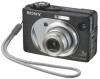
...diagram, printed wiring board and electrical and 5-10 to 5-13 parts list of processing the flexible boards/harnesses are shown. DIGITAL STILL CAMERA The above-described information is shown in Lens Frame Installation • Exchange Method of Barrier Assy • HELP: Sheet ...Model SPECIFICATIONS SERVICE NOTE DISASSEMBLY BLOCK DIAGRAMS PRINTED WIRING BOARDS FRAME SCHEMATIC DIAGRAM REPAIR PARTS LIST SCHEMATIC DIAGRAMS • For ADJUSTMENTS (SECTION 6), refer to SERVICE MANUAL, ADJ (987673651.pdf). • For INSTRUCTION MANUAL, refer to 4-48 the CH-146, SY-102, SW-422,...
...diagram, printed wiring board and electrical and 5-10 to 5-13 parts list of processing the flexible boards/harnesses are shown. DIGITAL STILL CAMERA The above-described information is shown in Lens Frame Installation • Exchange Method of Barrier Assy • HELP: Sheet ...Model SPECIFICATIONS SERVICE NOTE DISASSEMBLY BLOCK DIAGRAMS PRINTED WIRING BOARDS FRAME SCHEMATIC DIAGRAM REPAIR PARTS LIST SCHEMATIC DIAGRAMS • For ADJUSTMENTS (SECTION 6), refer to SERVICE MANUAL, ADJ (987673651.pdf). • For INSTRUCTION MANUAL, refer to 4-48 the CH-146, SY-102, SW-422,...

Service Manual
Page 3
...of unleaded solder are "pinched" or contact high-wattage resistors. 3. Look for parts which, through functioning, show obvious signs of your repair for unsoldered or poorly-soldered connections. Unleaded solder Boards requiring use of the circuit board (within 3 times). • Be careful ... lead free mark due to the customer and recommend their replacement. 5. REPLACE THESE COMPONENTS WITH SONY PARTS WHOSE PART NUMBERS APPEAR AS SHOWN IN THIS MANUAL OR IN SUPPLEMENTS PUBLISHED BY SONY. ATTENTION AU COMPOSANT AYANT RAPPORT À LA SÉCURITÉ! DSC-W1/W12 SAFETY-RELATED...
...of unleaded solder are "pinched" or contact high-wattage resistors. 3. Look for parts which, through functioning, show obvious signs of your repair for unsoldered or poorly-soldered connections. Unleaded solder Boards requiring use of the circuit board (within 3 times). • Be careful ... lead free mark due to the customer and recommend their replacement. 5. REPLACE THESE COMPONENTS WITH SONY PARTS WHOSE PART NUMBERS APPEAR AS SHOWN IN THIS MANUAL OR IN SUPPLEMENTS PUBLISHED BY SONY. ATTENTION AU COMPOSANT AYANT RAPPORT À LA SÉCURITÉ! DSC-W1/W12 SAFETY-RELATED...

Service Manual
Page 55
...-100, ST-101 FLEXIBLE, US-011 FLEXIBLE, 5. REPAIR PARTS LIST EXPLODED VIEWS ELECTRICAL PARTS LEVEL 3 ✕... MS-205, FLEXIBLE, JK-263, SP-045 FLEXIBLE) 9-876-736-51 Sony EMCS Co. 2004D0500-1 ©2004.4 Published by DI Technical Support Section DISASSEMBLY... name varies depending on the version of LEVEL 2 and LEVEL 3 Service Manual CONTENTS LEVEL 2 1. Contents of Automatic Adjustment Program. BLOCK DIAGRAMS OVERALL POWER... parts and boards CAMERA SECTION ADJUSTMENTS PREPARATIONS BEFORE ADJUSTMENTS ADJUSTMENT PROGRAMS VIDEO SYSTEM ADJUSTMENTS CAMERA SYSTEM ADJUSTMENTS LCD ...
...-100, ST-101 FLEXIBLE, US-011 FLEXIBLE, 5. REPAIR PARTS LIST EXPLODED VIEWS ELECTRICAL PARTS LEVEL 3 ✕... MS-205, FLEXIBLE, JK-263, SP-045 FLEXIBLE) 9-876-736-51 Sony EMCS Co. 2004D0500-1 ©2004.4 Published by DI Technical Support Section DISASSEMBLY... name varies depending on the version of LEVEL 2 and LEVEL 3 Service Manual CONTENTS LEVEL 2 1. Contents of Automatic Adjustment Program. BLOCK DIAGRAMS OVERALL POWER... parts and boards CAMERA SECTION ADJUSTMENTS PREPARATIONS BEFORE ADJUSTMENTS ADJUSTMENT PROGRAMS VIDEO SYSTEM ADJUSTMENTS CAMERA SYSTEM ADJUSTMENTS LCD ...

Service Manual
Page 82
In this case, the Test mode is not released even if the camera is turned off, thus requiring extreme care. • After completing adjustments/repairs, release the data setting. 1) Select page: 00, address: 01, and set data: 01. 2) Select page: 2F, address: 23, and set data: 00. 2. Setting ... 23 Data 80 00 01 02 03 04 05 Function Normal Forced SET UP mode Forced MOVIE mode Forced PLAY mode Forced CAMERA (Auto) mode Forced CAMERA (Program Auto) mode Forced CAMERA (Manual) mode • Before setting the data, select page: 00, address: 01, and set data: 01. • For page: 2F, ...
In this case, the Test mode is not released even if the camera is turned off, thus requiring extreme care. • After completing adjustments/repairs, release the data setting. 1) Select page: 00, address: 01, and set data: 01. 2) Select page: 2F, address: 23, and set data: 00. 2. Setting ... 23 Data 80 00 01 02 03 04 05 Function Normal Forced SET UP mode Forced MOVIE mode Forced PLAY mode Forced CAMERA (Auto) mode Forced CAMERA (Program Auto) mode Forced CAMERA (Manual) mode • Before setting the data, select page: 00, address: 01, and set data: 01. • For page: 2F, ...


